Power / Solar Panels
Installation Guide for Xantrex Solar Max Flex Panel
Comprehensive installation and maintenance guide for Xantrex Solar Max Flex Panels. Includes wiring diagrams, mounting instructions, safety precautions, and troubleshooting steps for 110W, 220W, and 330W models.
Table of contents
Manual images
Click an image to enlargeQuick Guide from the Manual
This guide provides essential instructions for installing and maintaining Xantrex Solar Max Flex Panels. Before beginning, ensure you have planned your power system, identified vehicle cable entry points, and gathered necessary tools like a wrench set and torque driver. Always follow safety codes and consult a certified technician for system design and installation.
Safety Information
Electrical Shock and Fire Hazard:
- The power system must be designed by a certified vehicle solar system designer and installed by a certified solar system technician.
- Disconnect all power sources and secure disconnect devices before working.
- Do not ground any PV conductors.
- Do not install the solar panel on top of a residential structure.
- Do not operate the panel if it is damaged.
- Use insulated tools when working with electrical equipment.
- Remove personal metal items like rings and watches before working.
Basic Installation Steps
1. Plan the power system: Draw your power system on paper. Identify vehicle cable entry points (factory-installed or vents). Locate a suitable, accessible, and moisture-free area for the charge controller.
2. Mount the solar panel:
- Prepare the roof surface by removing dust, dirt, and debris. Clean and degrease with isopropyl alcohol and dry completely.
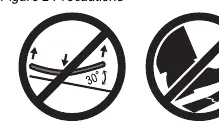
- Do not bend the panel more than 30 degrees.
- Do not step on the solar panel.
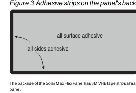
- Peel the liner from the 3M VHB tape and place the panel on the intended location.
- Apply even pressure on the areas with 3M VHB tape using a roller or the palm of your hands. Do not apply hard pressure on the solar cells.
Solar Panel Wiring
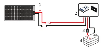
Connecting DC Cables:
- Cover the solar panel with a blanket or packaging box to de-energize it.
- Connect the red positive (+) and black negative (-) PV cables to the solar panel using MC4-type connectors.
- Route cables through the roof entry point to the charge controller.
- Connect battery cables to the charge controller and then to the battery terminals.
- Secure all cables with clamps or cable ties.
- Check polarity at all terminals before final connection.
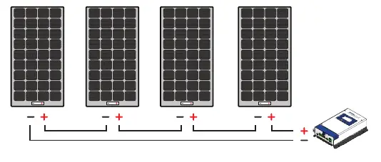
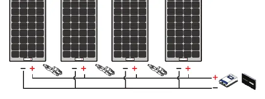
Configurations: Panels can be configured in series, parallel, or a combination of both depending on your power needs and charge controller type (PWM or MPPT).
Solar Panel Maintenance and Care
Perform a visual inspection monthly to check for sharp objects, corrosion, burnt hotspots, or shading. Clean the panel periodically if dust or dirt accumulates:
- Clean in the early morning or early evening when the panel is cooler.
- Use a soft cloth with clean water and mild detergent or soap.
- Do not use abrasive materials, chemicals, or pressure washers.
- Ensure no soap residue remains.
- Avoid water with high mineral content.
Troubleshooting
If the battery does not charge even in sunlight:
- Check for partial shading or insufficient sunlight; move the vehicle to direct sunlight.
- Check for loose or disconnected DC cables; tighten terminal connections.
- Check if the in-line fuse is blown; replace with a 30A/32V green ATC blade fuse.
Specifications
Specifications vary by model (110W, 110W Slim, 220W, 330W). Key parameters include:
- Maximum System Voltage: 600 VDC.
- Cell Type: Monocrystalline PERC.
- Safety: Class III PV Module (110W models) or Class II PV Module (220W/330W models).
Practical help
Common problems
Battery does not get charged even when sunlight is present.
Ensure the panel is not shaded. Check for loose DC cable connections and tighten them. Check if the in-line fuse is blown and replace with a 30A/32V green ATC blade fuse.
Before use
- Plan the power system on paper.
- Identify vehicle cable entry points.
- Gather tools: wrench set and torque driver.
- Clean and degrease the roof mounting surface with isopropyl alcohol.
- Verify polarity (Pos/Neg) before making final DC connections.
Specs in practice
- Maximum power at STC
- The power output of the panel under Standard Test Conditions (1000W/m2 irradiance, 25°C cell temperature).
- Open circuit voltage
- The voltage of the panel when no load is connected.
- Short circuit current
- The current flowing when the panel terminals are shorted.
Images and diagrams
- Figure 1: Cable schematic showing the connection between the solar panel, charge controller, DC fuse, and battery.
- Figure 5: Cable schematic for series configuration.
- Figure 6: Cable schematic for parallel configuration.
- Figure 7: Cable schematic for combination configuration.
Model compatibility
- Compatible with 12V or 24V batteries.
- Requires a solar charge controller (PWM or MPPT).
- Do not ground any PV conductors.

Manual page author
Michael Turner
Technical manual editor
Reviews PDF manuals for structure, safety notes, and practical product details so readers can find the right information quickly.