Power / Power Inverters
Owner's Guide for Xantrex Freedom X 1200 PRO Sine Wave Inverter
Quick guide for the Xantrex Freedom X 1200 PRO 120VAC 12VDC Sine Wave Inverter. Includes installation, wiring, configuration, operation, and troubleshooting steps.
Table of contents
Manual images
Click an image to enlargeQuick guide from the manual
This guide provides essential information for installing, operating, and troubleshooting the Xantrex Freedom X 1200 PRO 120VAC 12VDC Sine Wave Inverter. This unit is designed for recreational, commercial, and fleet vehicle installations. Always ensure installation is performed by qualified personnel in accordance with local electrical codes.
Safety Instructions
DANGER: Electrical shock and fire hazard. Installation must be performed by qualified personnel. Never operate the unit with the wiring compartment cover removed. Always disconnect all AC and DC power sources before servicing.
- Do not expose the unit to rain, snow, or liquids.
- Do not install in engine compartments or areas requiring ignition-protected equipment.
- Ensure the unit is mounted in a well-ventilated area with adequate clearance.
- Use insulated tools when working with electrical equipment.
Installation
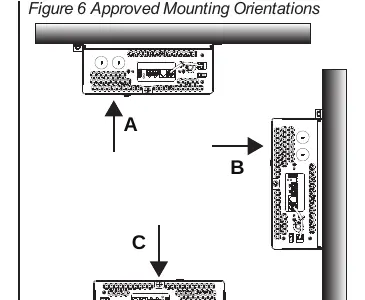
Mounting: The unit can be mounted under a horizontal surface, in a horizontal position on a vertical surface, or on a horizontal surface. Ensure at least 5 inches of clearance at the fan end for airflow.
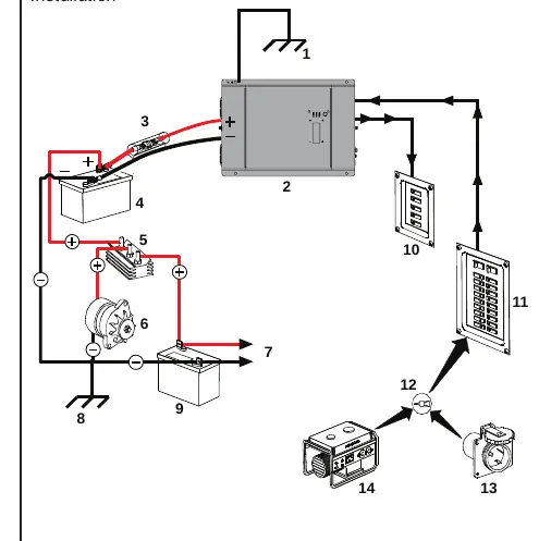
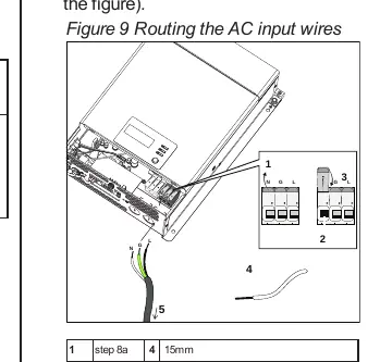
AC Wiring: Connect AC input and output wires to the terminal blocks inside the wiring compartment. Use appropriate strain relief clamps. Ensure wires are matched to Neutral (N), Ground (G), and Line (L) terminals.
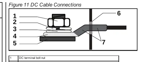
DC Wiring: Use stranded, copper wire rated for at least 90°C. Tighten DC terminal nuts to 71–89 in-lb (8–10 N-m). Ensure correct polarity; reversing positive and negative cables will blow a fuse and void the warranty.
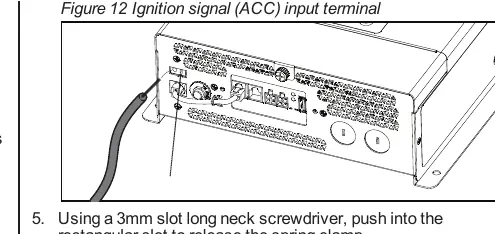
Ignition Control: The unit can be wired to inhibit operation in the absence of a vehicle ignition signal. Connect the ignition control wire to the ACC input terminal.
Operation
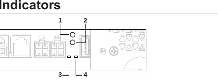
Display Panel: The display panel shows status information, error codes, and allows configuration. Use the Power button to turn the unit on or to Standby.
Configuration Mode: Press and hold the OK button for three seconds to enter configuration mode. Use the Scroll button to cycle through settings such as Power Save Timer, LBCO Voltage, and Ignition Control.
Battery Mode: The unit enters battery mode when shore power is unavailable and the unit is ON. The green status LED indicates the unit is supplying power from the battery.
Troubleshooting
If the unit displays an error code, refer to the following:
- E01: Low battery voltage shutdown. Check battery status and DC cable sizing.
- E02: High battery voltage shutdown. Check external charging sources.
- E03: AC output overload shutdown. Reduce connected loads.
- E04: Over-temperature shutdown. Check ventilation and reduce load.
- E07: Fan lock alarm. Check for obstructions in the fan grille.
For further assistance, contact Xantrex customer service at 1 800 670 0707 (USA/Canada) or +1 408 987 6030 (International), or visit https://xantrex.com/.
Official resources from the manual
Practical help
Common problems
No output voltage
Check AC shore power, verify battery voltage, ensure the unit is ON, and check for error codes on the LCD.
Alarm does not sound
Check if the alarm buzzer is muted in the configuration settings.
Fan turns on and off
This is normal operation when the unit is running at high power or high temperature.
Inverter won't start
Check ignition signal (if enabled), verify battery voltage, and ensure DC connections are secure.
Before use
- Verify battery voltage is 12V.
- Ensure all DC connections are tight and torqued to 71-89 in-lb.
- Check that the unit is mounted in a dry, well-ventilated area.
- Confirm AC input/output wiring is correct and properly grounded.
- Ensure the unit is not installed in an engine compartment.
Specs in practice
- Continuous Power
- 1200W at 25°C.
- Input Voltage
- 12VDC nominal.
- Output Voltage
- 120VAC (configurable 50/60Hz).
- Transfer Time
- <20ms.
Images and diagrams
- Figure 5: Typical RV installation showing battery, inverter, and AC panels.
- Figure 9: Routing AC input wires through strain relief.
- Figure 11: DC cable connection details including washers and lugs.
- Figure 12: Ignition signal (ACC) input terminal connection.
Model compatibility
- Designed for deep cycle lead-acid batteries.
- Not intended for charging batteries.
- Requires 12V battery bank (100Ah or more recommended).

Manual page author
David Miller
Documentation analyst
Organizes user manual content into clear summaries, with attention to model details, product context, and everyday usability.