Furniture / Beds & Mattresses
Assembly Instructions for VELVORO 180x200 Bed Frame
Comprehensive assembly guide for the VELVORO 180x200 bed frame. Includes step-by-step installation instructions, LED lighting setup, and safety guidelines.
Quick answers from the manual
Quick answer
- This document provides step-by-step assembly instructions for the VELVORO 180x200 bed frame, including the installation of the LED lighting system and the mattress support mechanism. p. 1, 24
Key actions
- Assemble the main bed frame structure. p. 1, 6
- Install the LED lighting system. p. 12, 15
- Install the mattress support mechanism. p. 16, 21
Problems and fixes
Bed frame feels unstable
Check all bolts (A1, A3, A5) and ensure they are fully tightened. Verify the frame is square.
p. 23Technical specifications
| Parameter | Value | Meaning | Pages |
|---|---|---|---|
| Max Load | 120kg | Maximum weight capacity per side. | p. 23 |
Where to find it in the PDF
- Frame Assembly p. 1, 6
- LED Installation p. 12, 15
- Mechanism Assembly p. 16, 21
Table of contents
Manual images
Click an image to enlargeQuick guide from the manual
This document provides detailed assembly instructions for the VELVORO 180x200 bed frame. The assembly process involves constructing the main frame, installing the LED lighting system, and setting up the mattress support mechanism. Please ensure you have enough space and the necessary tools (screwdriver, hammer) before beginning. The estimated assembly time is approximately 2 hours.
Assembly Preparation
Before starting, verify that all parts listed in the inventory are present. The hardware is categorized by type (A, E, L, etc.). Ensure you have a clear, flat surface to work on to prevent damage to the bed components.
Frame Assembly
The frame assembly is divided into several steps:
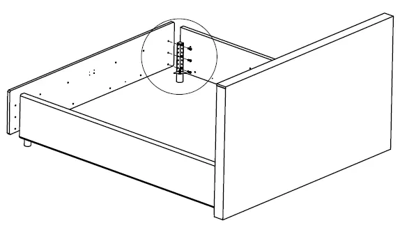
- Corner Assembly: Connect the side panels to the corner posts using the provided screws (A1). Ensure all connections are tight and the frame is square.
- Support Beams: Install the central support beams and legs. Use the hammer to insert dowels (A2) where required.
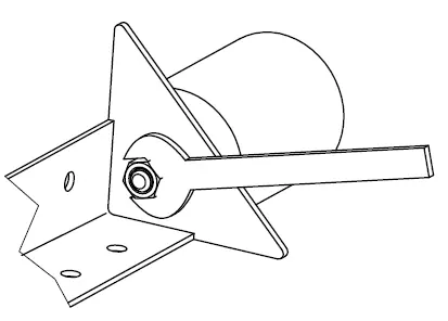
- Hardware Tightening: Use the provided wrench to secure the mechanism bolts (E_1, E_2). Ensure the orientation is correct as shown in the diagrams.
LED Lighting Installation
The bed includes an integrated LED lighting system. Follow these steps for installation:
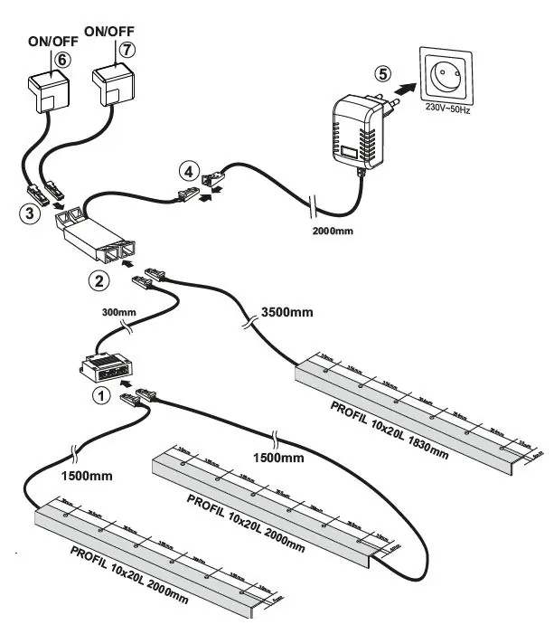
- Attach the LED profiles (11, 12, 13) to the frame using the provided screws (LW2).
- Connect the LED strips (L4, L5) to the control unit (1, 2).
- Route the cables carefully along the frame to avoid pinching.
- Connect the power adapter (5) to a standard 230V-50Hz outlet.
Mechanism Assembly
The mattress support mechanism allows for storage access:
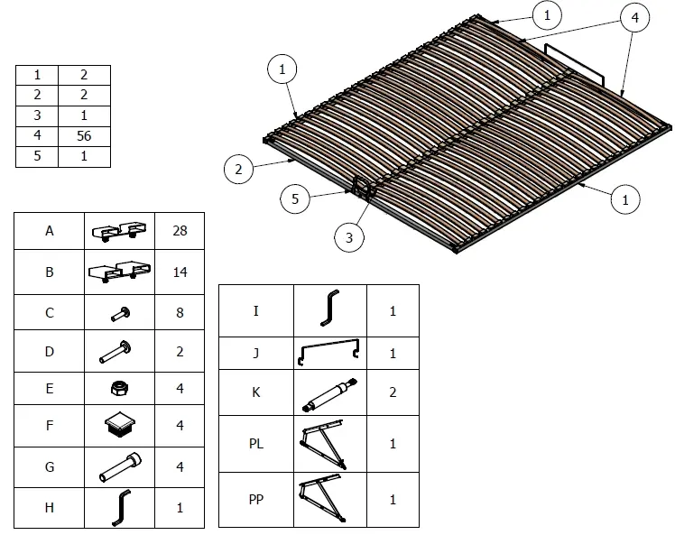
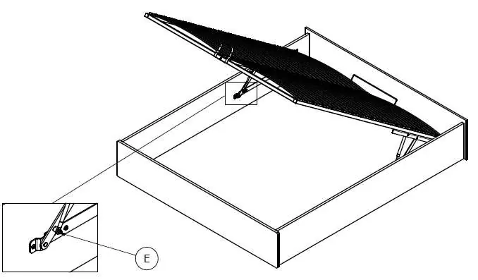
- Attach the hinges and gas springs (K) to the frame.
- Ensure the gas springs are oriented correctly.
- Attach the slat support frame to the hinges.
- Safety Warning: Do not sit on the bed while the mattress support is in the raised position.
Safety and Maintenance

- Weight Limit: The maximum weight capacity is 120kg per side.
- Cleaning: Use a soft, damp cloth to clean the surfaces. Do not use harsh chemicals or abrasive cleaners.
- Usage: Always lift the bed frame using the handle. Ensure the mechanism is fully engaged before accessing the storage area.
- Safety: Keep small parts away from children during assembly.
Manufacturer information
XXXLutz
Practical help
Common problems
Bed frame feels unstable
Check all bolts (A1, A3, A5) and ensure they are fully tightened. Verify the frame is square by measuring the diagonals (B=A).
LED lights not working
Verify all connections (L1-L7) are secure and the power adapter (5) is plugged into a 230V-50Hz outlet.
Before use
- Ensure all parts are present according to the parts list.
- Have a screwdriver and hammer ready.
- Clear enough space for assembly.
- Verify the frame is square (measure diagonals B=A).
- Check that all bolts are tightened.
Images and diagrams
- Diagrams show numbered parts and corresponding hardware.
- Arrows indicate direction of assembly or movement.
- Checkmarks indicate correct assembly, X marks indicate incorrect assembly.
Model compatibility
- Designed for 180x200cm mattresses.

Manual page author
David Miller
Documentation analyst
Organizes user manual content into clear summaries, with attention to model details, product context, and everyday usability.