Lighting / Fixtures
Installation Guide for Z-Lite 1943P32-MGLD Glacier Pendant Chandelier
Step-by-step installation and wiring guide for the Z-Lite 1943P32-MGLD Glacier Pendant Chandelier. Includes assembly instructions, wiring diagrams, and safety precautions.
Quick answers from the manual
Quick answer
- This document provides assembly and installation instructions for the Z-Lite 1943P32-MGLD Glacier Pendant Chandelier, including wiring diagrams and safety warnings. p. 1
Key actions
- Turn off power at the circuit breaker before starting. p. 1
- Connect wires: ground to ground, white to white/ridge, black to black/smooth. p. 1
- Install glass sheet using handle screws, ensuring they are not overtightened. p. 1
Where to find it in the PDF
- Installation Instructions p. 1
Table of contents
Quick Guide for Installation
This guide provides instructions for the assembly and installation of the Z-Lite 1943P32-MGLD Glacier Pendant Chandelier. Before beginning, ensure you have turned off the power at the circuit breaker and verified all parts are present. Always consult local electrical codes for wiring and grounding requirements.
Safety Precautions
- Power Off: Always shut off power at the fuse or circuit breaker box before starting any installation.
- Grounding: Ensure the mounting plate is installed with the side marked "GND" facing outward.
- Handling: Do not overtighten the handle screws when securing the glass sheet to avoid damage.
- Wattage: Do not exceed the maximum wattage rating specified for the fixture.
Assembly and Installation Steps
- Preparation: Shut off power and remove the old fixture. Unpack the new fixture and lay out all parts.
- Mounting Plate: Thread the two mounting screws into the mounting plate, spaced to match the canopy holes. Attach the plate to the outlet box.
- Pipe Assembly: Determine the desired height. Feed wires and the safety cable through the pipes, frame, and canopy. Connect the pipes to the lamp holder and secure the canopy.
- Safety Cable: Feed the safety cable through the small holes in the side of the column nut and lock it securely with the screws.
Wiring Instructions
Connect the electrical wires as follows:
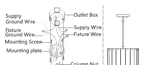
- Ground Wire: Attach the fixture ground wire to the supply ground wire using a wire nut, or attach to the mounting plate using the green ground screw.
- White Wire: Attach the fixture white wire to the supply white wire or ridge wire from the power source using a wire nut.
- Black Wire: Attach the fixture black wire to the supply black wire or smooth wire from the power source using a wire nut.
- Verification: Ensure all wire connectors are secured and cannot be pulled off with a slight tug. Tuck wires carefully inside the outlet box.
Final Assembly
Raise the canopy to the outlet box, align the screws on the mounting plate with the holes in the canopy, and lock it securely with the finials. Install the light bulbs (not included) according to the fixture's specifications. Finally, raise the glass sheet to the frame side and use the handle screws to secure the glass sheet and plastic shim onto the frame.
Practical help
Common problems
Glass sheet is loose or tight
Adjust the handle screws carefully. Do not overtighten, as this may damage the glass or frame.
Fixture not secure to ceiling
Ensure the mounting plate is firmly attached to the outlet box and the canopy is locked securely with the finials.
Before use
- Shut off power at the circuit breaker
- Verify all parts are present
- Determine the required number of pipes for desired height
- Check local electrical codes for wiring and grounding
- Ensure wire connectors are tight and secure
Show more Show less
Specs in practice
- Maximum Wattage
- Do not exceed the fixture's specified maximum wattage rating when installing bulbs.
Images and diagrams
- Wiring diagram illustrates the connection of supply ground to fixture ground, supply white to fixture white, and supply black to fixture black.
- Parts diagram shows the assembly order of the pipes, canopy, frame, and glass sheet.
Model compatibility
- Requires standard outlet box installation.
- Bulbs are not included.

Manual page author
David Miller
Documentation analyst