Lighting / Fixtures
Installation Manual for Z-Lite 1100-1S-CH Wall Sconce
Quick installation guide for the Z-Lite 1100-1S-CH wall sconce. Includes step-by-step wiring instructions, grounding procedures, and assembly steps for proper setup.
Quick answers from the manual
Quick answer
- This manual provides instructions for the safe installation and assembly of the Z-Lite wall sconce, including wiring, grounding, and final assembly steps. p. 1
Key actions
- Secure the universal mounting plate to the outlet box using outlet box screws. p. 1
- Connect the ground wire from the fixture to the green grounding screw on the circular strap, then to the ground wire from the outlet box. p. 1
- Identify fixture wire group (A or B) and connect to the corresponding house wire (Black or White) using wire connectors. p. 1
- Assemble the backplate to the mounting plate, secure the glass, and install the light bulb. p. 1
First start
- Ensure electricity is shut off at the fuse or circuit breaker before beginning installation. p. 1
- Remove the fixture from the carton and verify all parts are included. p. 1
Show 2 more answers Show less
Maintenance and reset
- Wipe the fixture with a soft cloth and clean the glass with mild soap. Avoid abrasive materials. p. 1
Where to find it in the PDF
- Installation and Safety Instructions p. 1
Table of contents
Quick Guide for Installation
Before starting, ensure the electricity is turned off at the circuit breaker or fuse box. This fixture requires standard tools and basic electrical knowledge. If you are unsure about the wiring, consult a qualified electrician. Proper wiring is essential for the safe operation of this fixture.
Fixture Assembly and Installation
Follow these steps to install your Z-Lite fixture:
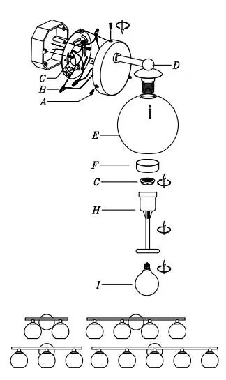
- Mounting: Secure the universal mounting plate (B) to the outlet box using the provided outlet box screws.
- Grounding: Insert the green grounding screw into the hole with two raised dimples on the circular strap. Wrap the fixture ground wire around the screw and connect it to the house ground wire using a wire connector (not supplied).
- Wiring: Identify your fixture wires. Group A (Black, smooth, or wire with tracer) connects to the Black house wire. Group B (White, ridged, or wire without tracer) connects to the White house wire.
- Connections: Place wires together, apply a wire connector, and screw clockwise until firm. Test the connection by gently pulling on the connector. Ensure no bare wires are visible outside the connectors.
- Final Assembly: Tuck wires into the outlet box. Attach the backplate to the mounting plate and secure it with screws. Slide the glass (E) over the socket, then secure with the retaining ring (G) and metal cover (F) using the spacer tool (H).
- Bulb Installation: Install the light bulb (not included). Do not exceed the maximum capacity recommended on the socket.
Cleaning and Maintenance
Wipe the fixture with a soft cloth. Clean the glass using a mild soap. Do not use abrasive materials, scouring pads, steel wool, or abrasive powders, as these can damage the finish.
Practical help
Common problems
Fixture does not turn on
Check wire connections and ensure power is restored at the circuit breaker.
Wire connector pulls off
Re-do the connection, ensuring wires are not twisted together before applying the connector and screwing it on firmly.
Fixture is loose on the wall
Ensure the backplate is securely tightened to the universal mounting plate using the mounting screws.
Before use
- Turn off electricity at the fuse or circuit breaker.
- Verify all parts are included (screws, mounting plate, glass, etc.).
- Identify house wire colors (Black/White/Ground).
- Ensure you have wire connectors (not supplied).
Show more Show less
Specs in practice
- Group A Wire
- Connects to Black house wire; includes smooth or tracer wires.
- Group B Wire
- Connects to White house wire; includes ridged or non-tracer wires.
- Parallel Wire (SPT-1 & SPT-2)
- Tracer wire is square/ridged; non-tracer wire is round/smooth.
Images and diagrams
- The diagram shows the assembly order from the mounting plate (B) to the glass (E) and bulb (I).
Model compatibility
- Instructions apply to models: 1100-1S, 1100-2V, 1100-3V, 1100-4V, and 1100-5V.

Manual page author
Emily Carter
User documentation editor