Lighting / Fixtures
Installation Manual for Zevni Berton 2-Light Vanity Light A04675
Quick installation guide for the Zevni Berton 2-Light Vanity Light (A04675). Includes step-by-step wiring instructions, safety warnings, and tool requirements.
Quick answers from the manual
Quick answer
- This manual provides installation instructions for the Zevni Berton 2-Light Vanity Light (A04675), including wiring, mounting, and bulb installation. p. 1, 2, 3
Key actions
- Turn off power p. 1, 2
- Install fixture p. 2, 3
First start
- Ensure power is off, connect wires according to the diagram, secure the back plate, and install bulbs. p. 3
Show 4 more answers Show less
Problems and fixes
Back plate not snug against wall
Adjust the threaded length of the pre-assembled mounting screws on the mounting plate.
p. 3Maintenance and reset
- Wipe the fixture with a soft cloth. Clean glass with a mild, non-abrasive soap. p. 3
Technical specifications
| Parameter | Value | Meaning | Pages |
|---|---|---|---|
| Voltage | 120V | Required power supply | p. 1 |
| Max Wattage | 40W | Maximum wattage per bulb | p. 1 |
Where to find it in the PDF
- Safety and Tools p. 1
- Parts and Assembly p. 2
- Wiring and Final Steps p. 3
Table of contents
Manual images
Click an image to enlargeQuick guide from the manual
This document provides instructions for the safe installation of the Zevni Berton 2-Light Vanity Light (A04675). Before beginning, ensure the power is turned off at the main fuse or circuit breaker. The installation should be performed by a licensed electrician. The fixture requires a 120V power supply and supports a maximum of 40W per bulb.
Parts Included
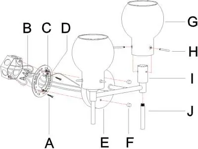
- Mounting plate (D)
- Back plate (E)
- Knob nuts (F)
- Glass shades (G)
- Screws (H)
- Sockets (I)
- Lower tubes (J)
- Green ground screw (C)
- Mounting screws (A)
- Plastic wire connectors (B)
Assembly & Installation Instructions
Step A1: Remove knob nuts (F) from the back plate (E) and set them aside. Screw the lower tubes (J) onto the bottom of the sockets (I).
Step A2: Pass the supply wires from the outlet box through the mounting plate (D). Secure the mounting plate (D) to the outlet box using the mounting screws (A).
Step A3: Make wire connections as shown in the wiring diagram. Ensure the ground wire is connected to the bare copper wire. Twist wires together with plastic wire connectors, wrap with electrical tape, and tuck all wires into the outlet box.
Step A4: Align the holes in the back plate (E) with the pre-assembled mounting screws on the mounting plate (D). Attach the back plate and secure it with the knob nuts (F). If the back plate is not snug against the wall, adjust the threaded length of the mounting screws on the mounting plate.
Step A5: Place the glass shades (G) on the sockets (I) and secure them with screws (H). Install the bulbs (not included), ensuring they do not exceed the maximum wattage.
Wiring Guide
Connect the supply wires according to the following chart:
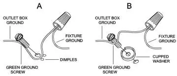
- Black or Red Supply Wire: Connect to Black fixture wire.
- White Supply Wire: Connect to White fixture wire.
- Ground Wire: Connect to the Green ground screw on the mounting plate.
Note: When using parallel wires (SPT I & SPT II), the neutral wire is square-shaped or ridged, while the other wire is round or smooth.
Cleaning & Maintenance
To clean the fixture, wipe it with a soft cloth. Clean the glass shades with a mild, non-abrasive soap. Do not use abrasive materials such as scouring pads, powders, steel wool, or abrasive paper.
Manufacturer information
ZEVNI
Practical help
Common problems
Back plate is not snug against the wall
Remove the back plate, unscrew the pre-assembled hex nuts on the mounting plate, adjust the threaded length of the mounting screws, and re-tighten the hex nuts.
Wire connection safety
Ensure no wire strands are exposed after connecting with plastic wire connectors and wrapping with electrical tape.
Before use
- Turn off electricity at the main fuse or circuit breaker
- Verify the voltage is 120V
- Ensure the mounting surface is clean, dry, and flat
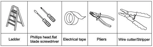
- Prepare required tools: ladder, Phillips/flat head screwdriver, electrical tape, pliers, and wire cutter/stripper
Show more Show less
Images and diagrams
- Wiring diagram illustrates proper connection of ground, black, and white wires
- Assembly sequence A1-A5 shows the step-by-step installation process
Model compatibility
- Requires 120V power supply
- Maximum 40W per bulb

Manual page author
David Miller
Documentation analyst