Electronics / AV Splitters
Installation Manual for ENFORCER 4K HDMI 1x4 Splitter/Extender MVE-AH1E4-42NQ
Quick installation guide for the ENFORCER 4K HDMI 1x4 Splitter/Extender (MVE-AH1E4-42NQ). Includes wiring diagrams, technical specifications, and troubleshooting steps for extending HDMI signals over Cat6.
Quick answers from the manual
Quick answer
- The MVE-AH1E4-42NQ is a 4K HDMI 1x4 Splitter/Extender that transmits audio and video over Cat6 cable up to 230ft (70m) at 1080p or 131ft (40m) at 4K. p. 1
Key actions
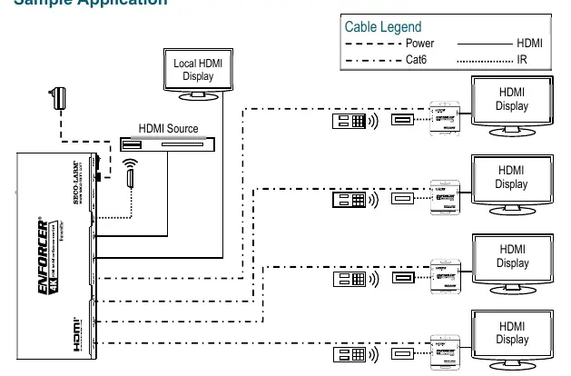
- Connect the transmitter to the source and the receivers to the displays using Cat6 cable, then power the transmitter. p. 3
Problems and fixes
HDMI device does not function correctly
Use T-568B wiring, ensure power, test Cat6 cable, and verify source/display by direct connection.
p. 4Technical specifications
| Parameter | Value | Meaning | Pages |
|---|---|---|---|
| Range | 131ft (40m) at 4K / 230ft (70m) at 1080p | Maximum transmission distance over Cat6 | p. 2 |
Where to find it in the PDF
- Product Overview p. 1, 2, 3
- Installation p. 3
- Troubleshooting p. 4
Table of contents
Manual images
Click an image to enlargeQuick guide from the manual
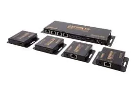
The ENFORCER 4K HDMI 1x4 Splitter/Extender (MVE-AH1E4-42NQ) is designed to extend HDMI audio and video signals over Cat6 cabling. The system includes one transmitter and four receivers, supporting resolutions up to 4K. It features IR pass-through for remote control operation from the display location and supports a local monitor via loop-out.
Parts List
- 1x Transmitter
- 4x Receivers
- 1x 12VDC Power adapter
- 1x IR Transmitter (with mounting tape)
- 4x IR Receivers (with mounting tape)
- 8x Mounting screws
- 1x Manual
Specifications
- Range: Up to 131ft (40m) at 4K@30Hz; up to 230ft (70m) at 1080p.
- Video Formats: HDMI 2.0b, HDCP.
- Audio Formats: LPCM, Dolby Digital, Dolby TrueHD, Dolby Digital Plus, DTS-ES, DTS HD Master, DTS HD-HRA, DTS-X.
- Wiring Standard: T-568B.
- Power: 12VDC (2.5A adapter included).
- Operating Temperature: 32°~104° F (0°~40° C).
Installation
- Determine the installation location and required length of Cat6 cable.
- Connect the transmitter to the HDMI output of the source device.
- Connect Cat6 cables to both the receiver and transmitter units. Note: For maximum range, use Cat6 cable.
- Connect the receiver to the HDMI input of the display device.
- Connect the 12VDC adapter to the transmitter.
- Install the IR transmitter to the IR Out port, pointing it at the device to be controlled. Install the IR receiver to the IR In port, pointing it where the remote control will be used.
- Switch on the HDMI source and display to verify the system is functioning.
Troubleshooting
If the HDMI device does not function correctly:
- Ensure the T-568B wiring standard is used.
- Verify that both the extender, source, and display are powered.
- Test the Cat6 cable for functionality.
- Verify the HDMI source and display by connecting them directly with an HDMI cable.
If experiencing screen flickering or image loss:
- Use a higher grade of twisted pair category cable (Cat6 recommended).
- Switch the source device to a lower HDMI output (e.g., 1080p instead of 4K).
- Restart the handshake process by powering everything down, then powering up and connecting each device in succession, starting with the HDMI source.
Practical help
Common problems
HDMI device does not function
Check power connections, verify T-568B wiring standard, and test the source directly to the display to rule out cable or source issues.
Screen flickering or brief image loss
Use higher grade Cat6 cable, lower the source resolution (e.g., to 1080p), or restart the handshake process by powering devices on in sequence starting with the source.
Before use
- Ensure Cat6 cable is used for the connection.
- Verify the T-568B wiring standard.
- Confirm the 12VDC power adapter is connected to the transmitter.
- Ensure the source and display devices are powered on.
- Position IR transmitters and receivers correctly for remote control operation.
Specs in practice
- Wiring Standard
- Must use T-568B standard for Cat6 cables.
- IR Pass-through
- Allows remote operation of the source device from the display location (30~60 kHz).
Images and diagrams
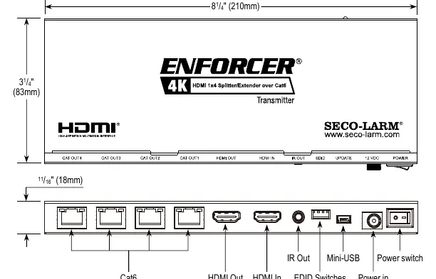
- Transmitter: Features HDMI In, HDMI Out (loop), IR Out, EDID switches, and Cat6 ports.
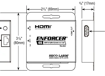
- Receiver: Features Cat6 input, HDMI Out, and IR In port.
Model compatibility
- Requires Cat6 cable for optimal performance.
- Supports HDMI 2.0b and HDCP.

Manual page author
Michael Turner
Technical manual editor
Reviews PDF manuals for structure, safety notes, and practical product details so readers can find the right information quickly.