HVAC / Heat Pumps
Installation Guide for ACiQ 20FD-MH Series Electric Furnace
A comprehensive installation guide for the ACiQ 20FD-MH Series Manufactured Housing Electric Furnace. This manual covers safety instructions, installation preparation, ductwork, electrical wiring, conversion kits, and air volume adjustment.
Quick answers from the manual
Quick answer
- The ACiQ 20FD-MH Series is a manufactured housing electric furnace. Installation requires adherence to local/national codes, proper ductwork sizing, and electrical connections for 208/240V power. It supports downflow and upflow configurations. p. 1, 2
Key actions
- Install ductwork p. 6
- Configure for Upflow p. 3, 5
- Adjust Air Volume p. 7, 8
First start
- Ensure all cabinet openings are sealed, check for condensate leakage, perform leak detection on refrigerant circuit, and secure all cabinet doors. p. 8
Show 4 more answers Show less
Problems and fixes
Improper heating
Check return air availability and ensure no obstructions.
p. 2
Low transformer voltage
Move transformer tap from 240V to 208V if supply is 208V.
p. 6Maintenance and reset
- Check filter every month. p. 3
Technical specifications
| Parameter | Value | Meaning | Pages |
|---|---|---|---|
| Voltage | 208/240V | Operating voltage | p. 6 |
| Heat Kits | 10-20 kW | Heating capacity | p. 2 |
Where to find it in the PDF
- Installation Guide p. 1, 10
Table of contents
Manual images
Click an image to enlargeQuick guide from the manual
This document provides installation and configuration instructions for the ACiQ 20FD-MH Series electric furnace. Key requirements include ensuring proper clearances (18 inches for alcove, 6 inches for closet), verifying electrical supply (208/240V), and ensuring proper ventilation in enclosed areas. Always disconnect all power sources before servicing.
Introduction and Cabinet
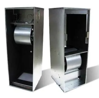
The EF**20FD-MH Series air handlers are designed for versatile installation, supporting both Downflow (Front Return) and Upflow (Bottom Return) configurations. The unit features a galvanized steel cabinet with painted doors, fully insulated with 1/2 inch faced insulation to provide high R-value. Units ship with a disposable filter in the filter rails.
Installation Preparation
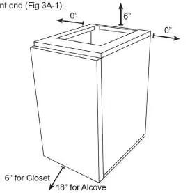
Before beginning, read all safety warnings. Ensure the unit is adequately sized; the tonnage of the outdoor unit should never exceed the tonnage of the furnace. A minimum clearance of 18 inches is recommended for alcove installations, and 6 inches for closet installations to ensure proper service access and airflow.
Coil Deck Reconfiguration
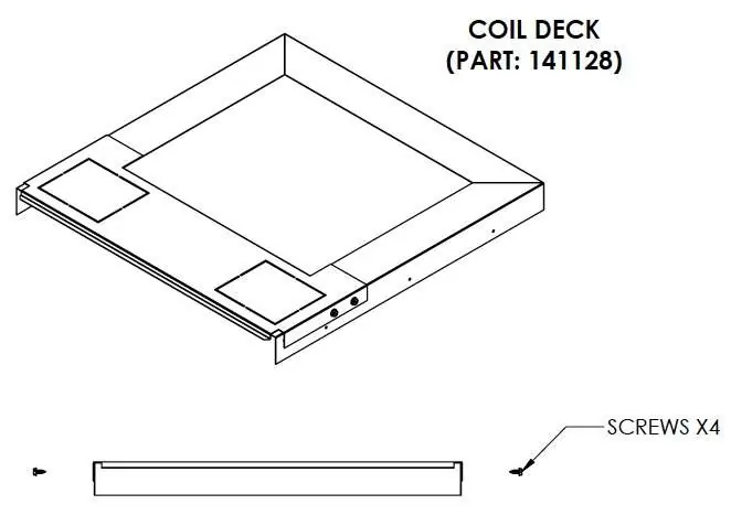
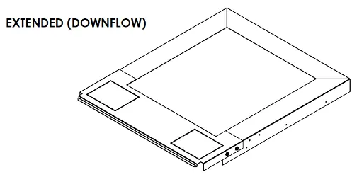
The coil deck can be reconfigured for different airflow orientations. To reconfigure, remove the coil deck from the unit and disassemble. Extend the coil assembly for downflow configurations or collapse it for upflow configurations as specified in the manual.
Conversion Kits
The unit supports conversion between different return and door configurations using specific kits (AEXK-01 and AEXK-02). Follow the specific steps provided for each kit, which include removing the door, filter, and top panels, mounting new filter rails, and installing the appropriate door type.
Ductwork and Duct Connector
Duct systems must be installed in accordance with NFPA 90A or 90B standards. Use non-flammable flexible collars for return air and discharge connections to prevent vibration. Ensure duct sizes are not smaller than the furnace flange openings. Seal the duct connector to the top of the duct using foam gasket and secure with screws.
Electrical Installation
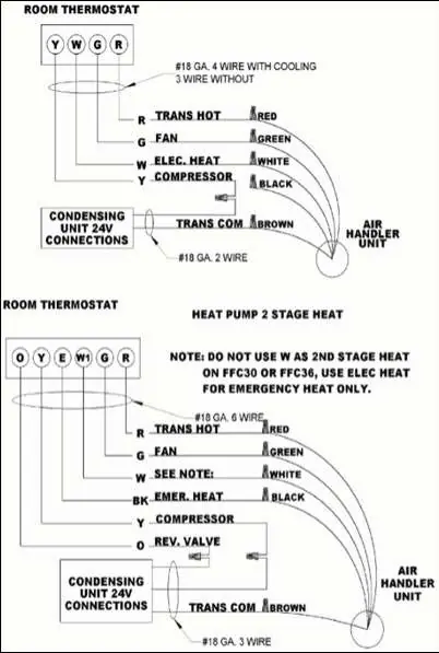
The units are designed for single or three-phase 208/240V, 60Hz power supply. Wiring must comply with the National Electric Code. For 208V supply, the transformer tap must be moved from 240V to 208V. Connect power wiring to the line side connections and ensure the ground wire is secured to the grounding lug.
Air Volume Adjustment
Air volume must be set to the level recommended by the outdoor unit manufacturer, typically around 400 CFM per ton of cooling capacity. Use the CFM tables provided in the manual to select the appropriate speed tap based on external static pressure. If static pressure exceeds 0.5 inches water column, reduce duct friction or obstructions.
Final System Checkout
After installation, ensure all cabinet openings are sealed and grommets are in place. Check for condensate leakage during cooling operation, perform leak detection on the refrigerant circuit, and secure all cabinet doors.
Manufacturer information
ACiQ
Practical help
Common problems
Improper heating or element failure
Ensure airflow is available to the return; check for obstructions in the duct system.
Secondary transformer voltage too low
If supplying 208V, move the transformer tap from 240V to 208V.
Condensate leakage
Check for leaks during the final system checkout with the cooling system operating.
Before use
- Inspect the unit for shipping damage upon receipt.
- Verify the model number and options match your order.
- Ensure proper clearances (18 inches for alcove, 6 inches for closet).
- Ensure the enclosed area is properly ventilated if installing near CO-producing devices.
- Disconnect all power sources before servicing or installing.
- Verify the outdoor unit tonnage does not exceed the furnace tonnage.
Show more Show less
Images and diagrams
- Fig 4A-1: Minimum clearance requirements for electric furnace.
- Fig 4B-1A/B: Orientation diagrams for Downflow and Upflow configurations.
- Fig 6A-1: Wiring diagram for single stage cooling with electric heat.
Model compatibility
- Requires 208/240V single or three-phase power.
- Not approved for outdoor installation.
- Requires specific conversion kits (AEXK-01/02) for different configurations.

Manual page author
David Miller
Documentation analyst