Tools / Measuring Tools
User Manual for AEMC Instruments 1210N/1250N Megohmmeter
Comprehensive user guide for the AEMC Instruments 1210N and 1250N hand-cranked megohmmeters. Includes setup, safety procedures, insulation resistance testing methods, connection diagrams for motors and transformers, and maintenance...
Table of contents
Manual images
Click an image to enlargeQuick guide from the manual
The AEMC 1210N and 1250N are hand-cranked megohmmeters designed for insulation resistance testing. Safety is the responsibility of the operator. Always perform a voltage test (safety check) before connecting the instrument to ensure the circuit is dead. During testing, ensure the crank speed LED (amber for 1210N, green for 1250N) is illuminated to guarantee a valid reading. If the LED is not ON, the reading is not valid.
Description
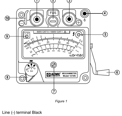
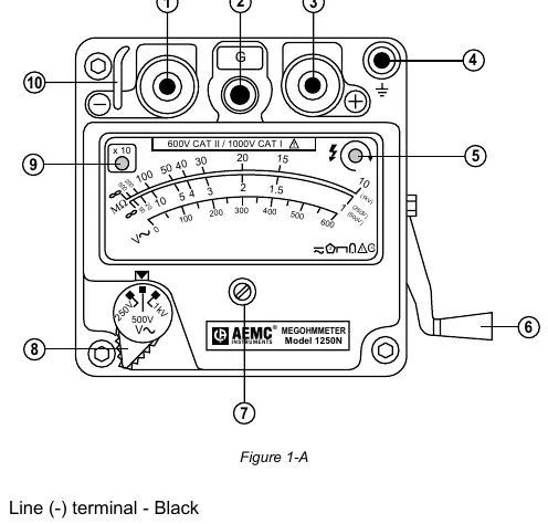
These instruments are compact, self-contained, and ruggedly built with an O-ring-sealed cast aluminum case. They feature an auto-ranging function that expands the scale by x10 when the pointer reaches the end of the scale, indicated by a red LED.
Operation
Safety Check - Voltage Test
Before measuring insulation resistance, confirm the sample is fully discharged and not connected to an energized circuit. Set the range selection to V (MΩ) and connect the leads. Read the voltage on the red scale (600VAC max). DO NOT CRANK during this test.
Insulation Resistance Testing
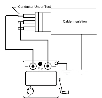
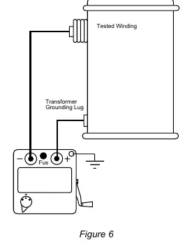
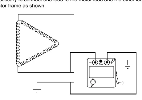
After confirming the circuit is dead, select the MΩ range. Connect the leads according to the specific application (cable, motor, or transformer). Crank the handle until the crank speed LED illuminates, ensuring the appropriate test voltage is reached.
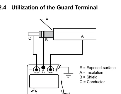
Utilization of the Guard Terminal (1250N only)
The guard terminal is used to eliminate surface leakage errors when measuring high resistance values. Connect the guard terminal to a shield or a copper wire wound around the exposed surface of the insulation.
Maintenance
The megohmmeter may be gently cleaned with a soft cloth, soap, and water. Dry immediately after cleaning. Do not allow water to penetrate the electronic module. For repair and calibration, contact the AEMC Service Center to obtain a Customer Service Authorization Number (CSA#) before returning the instrument.
Specifications
- 1210N Test Voltage: 500V DC
- 1250N Test Voltages: 250V, 500V, 1000V DC
- Accuracy: 2% to 2.5% of full scale length (depending on model/test)
- Power Supply: Hand-cranked brushless alternator
- Dimensions: 4.7 x 4.7 x 5.1 inches (120 x 120 x 130mm)
- Weight: 3.3 lbs (1.5 kg)
Practical help
Common problems
Reading is not valid
Ensure the crank speed LED is ON during testing. If it is not lit, the test voltage is insufficient.
Inaccurate measurement
Ensure the sample is fully discharged and not connected to an energized circuit before testing. If measuring on a DC circuit, the pointer may deflect but the measurement may be inaccurate.
High resistance measurement error
Use the guard terminal to eliminate surface leakage errors. If no shield is available, wind a copper wire around the exposed surface and connect it to the guard terminal.
Before use
- Check for live circuits using the voltage test (do not crank).
- Ensure the sample is fully discharged.
- Verify the instrument is grounded.
- Check that leads are in good condition.
- Ensure the crank speed LED illuminates during operation.
Specs in practice
- Auto-ranging
- Automatically expands the scale by x10 when the pointer reaches the end of the scale; indicated by a red LED.
- Guard Terminal
- Used to eliminate surface leakage errors when measuring high resistance.
- Crank Speed LED
- Indicates that the proper test voltage has been reached.
Images and diagrams
- Figure 1/1-A: Control panel layout and terminal identification.
- Figure 3-7: Connection diagrams for cables, transformers, and motors.
- Figure 13-15: Utilization of the guard terminal.
Model compatibility
- 1210N: 500V test voltage.
- 1250N: 250V, 500V, 1000V test voltages.

Manual page author
Emily Carter
User documentation editor
Prepares concise manual descriptions and highlights the most useful setup, operation, and maintenance information for readers.