HVAC / Refrigeration Controllers
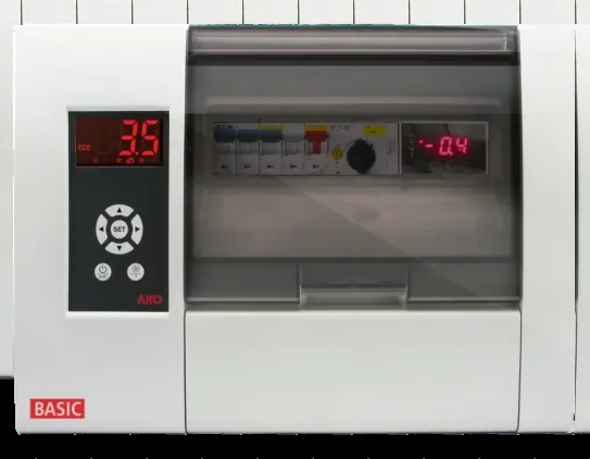
AKO 1569x PROPlus 3PH BASIC Electronic Panel
Quick guide for the AKO 1569x PROPlus 3PH BASIC Electronic Panel. Includes installation, wiring, configuration, alarm troubleshooting, and technical specifications.
Table of contents
Manual images
Click an image to enlargeQuick guide from the manual
The AKO 1569x PROPlus 3PH BASIC is an electronic panel designed for managing positive and negative cold room stores. Key operations include compressor control, defrost management, fan control, and light control. Before installation, ensure the power supply is disconnected. The unit requires qualified personnel for installation and maintenance. Always use AKO-supplied probes for correct operation.
Installation
To install the unit:
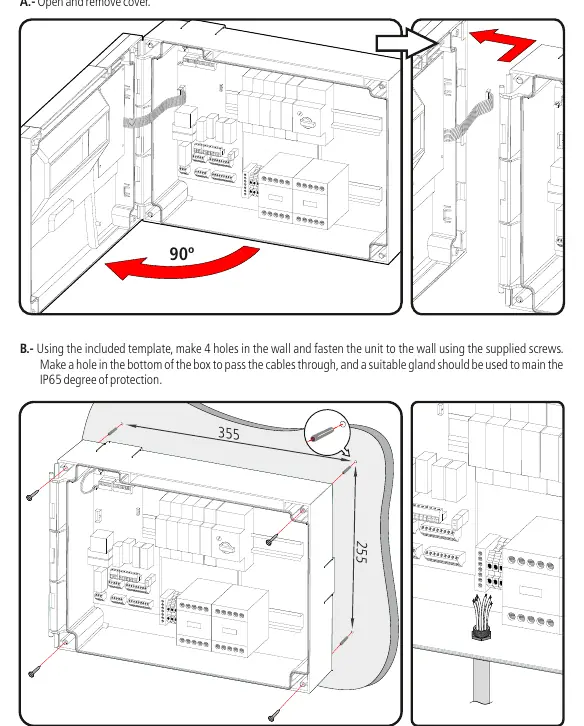
- Open and remove the cover.
- Use the included template to drill 4 holes in the wall.
- Fasten the unit to the wall using the supplied screws.
- Make a hole in the bottom of the box for cable entry and use a suitable gland to maintain the IP65 protection rating.
- Arrange wiring according to the provided diagrams.
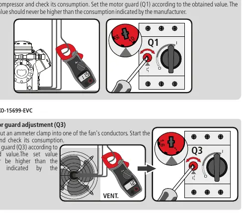
- Adjust the motor guard (Q1/Q3) based on the compressor or fan consumption.
- Replace the cover and front trims.
Operation and Control
The unit features several control modes:
- Compressor Control: Manages the compressor based on probe 1 temperature and set point (SP). Includes a continuous cycle mode for cooling before loading products.
- Defrost Control: Initiated by time (d0) or manual key press. Supports defrost by resistors.
- Fan Control: Controlled by probe 2 (evaporator) and parameters F0/F1.
- Pump Down Function: Prevents refrigerant movement issues by using a stop/start technique with the liquid solenoid and low-pressure switch.
Alarms and Troubleshooting
The unit displays specific codes for errors:
- E1/E2: Probe 1 or 2 faulty (open circuit or out of limits).
- AH/AL: Maximum/Minimum temperature alarm.
- AE/AES: External alarm or severe external alarm.
- Pd/LP: Pump down malfunction error.
- ASC: Compressor safety chain alarm.
Configuration and Parameters
The unit offers basic and advanced configuration menus:
- Basic Configuration: Press the SET key for 5 seconds to access common settings like Set Point (SP), defrost frequency (d0), and alarm limits (A1/A2).
- Advanced Configuration: Press the Up and Down keys for 10 seconds to access all parameters.
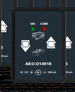
- Parameter Transfer: Use the AKO-D14918 programming key and AKO-80018 power supply to transfer settings between devices.
Connectivity
The unit includes an RS485 port for MODBUS communication. Up to 127 units can be connected to a PC using AKONet (AKO-5010) software or the AKO-5011 web server.
Technical Specifications
- Working Temperature: -5 ºC to 40 ºC.
- Protection: IP65.
- Power Supply: 400V / III 50/60 Hz.
- Probe Range: -45.0 ºC to 99.9 ºC.
Manufacturer information
AKO Group
Practical help
Common problems
E1 or E2 message on display
Probe 1 or 2 is faulty. Check for open circuit, crossover, or temperature outside limits (-50 to 99 ºC).
AH or AL message
Maximum or minimum temperature alarm triggered. Check if the temperature has reached the limits set in A1 or A2.
Pd or LP message
Pump down malfunction. Check the low-pressure switch and compressor safety chain.
ASC message
Compressor safety chain triggered. Check the motor guard, thermistors, or high-pressure controller.
Before use
- Disconnect power supply before handling the panel.
- Ensure the installation environment is free from dust, dirt, and moisture.
- Verify that the probes are supplied by AKO.
- Check that the motor guard (Q1/Q3) is set according to the manufacturer's consumption data.
- Ensure all power connections are tightened.
- Verify that the panel is closed and locked.
Specs in practice
- 400V / III 50/60 Hz
- Required power supply voltage and frequency for the unit.
- Probe range (-45 to 99.9 ºC)
- The operational temperature range for the connected NTC probes.
Images and diagrams
- Wiring diagrams for pressure switches (High/Low and Separate Low pressure).
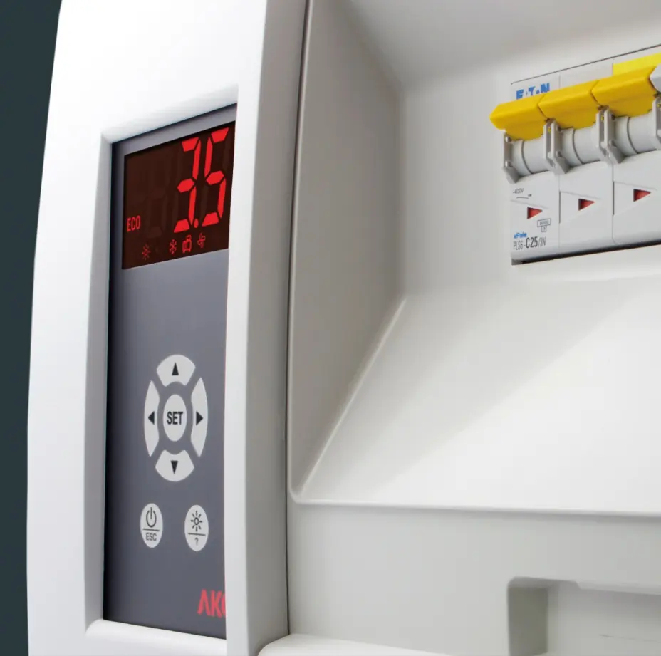
- Control panel layout showing display, browser keys, and status icons.
- Installation steps for mounting the panel and cable entry.
- Parameter transfer setup using the AKO-D14918 key.
Model compatibility
- Only use probes supplied by AKO.
- RS485 connectivity requires AKONet software or AKO-5011 web server.
- Auxiliary relays (AUX 1, 2, 3) are programmable depending on the model.

Manual page author
Emily Carter
User documentation editor
Prepares concise manual descriptions and highlights the most useful setup, operation, and maintenance information for readers.