Industrial / Data Loggers
User Manual for AKO CAMRegis Data Logger
Comprehensive user guide for the AKO CAMRegis data logger series (models AKO-15740, 15742, 15750, 15752, 15780, 15782). Includes detailed instructions for installation, wiring, configuration, and operation.
Table of contents
Manual images
Click an image to enlargeQuick guide from the manual
The AKO CAMRegis is a high-performance data logger designed to capture, store, and record physical variables such as temperature, humidity, and pressure. Before starting, ensure the device is installed in a location protected from vibrations, water, and corrosive gases. The unit requires a power supply of 100-240 Vac and must be installed by qualified personnel.
Key operational steps:
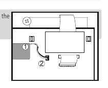
- Installation: Connect the battery cable to the panel connector before final installation.
- Wiring: Ensure the power supply circuit has a main switch rated at least 2 A, 230 V.
- Configuration: Access the programming menu by pressing the SET key for 5 seconds.
- Data Access: Use the SET key to consult recorded data by calendar or by block.
Installation
The device supports both wall and panel mounting. For panel mounting, ensure the panel thickness does not exceed 3 mm and replace the gasket with the included panel mounting gasket. Drill holes according to the specified dimensions (214 mm x 214 mm). For wall mounting, drill 3 holes to match the housing fixing points. Always connect the battery cable to the panel connector before securing the front cover.
Wiring and Connectivity
The device features specific terminals for power supply, alarms, and inputs. Always disconnect the power supply before making any connections. Use shielded cable for NTC probe extensions and connect the grid to ground. The device includes an RS485 (MODBUS) port for remote management using SOFTRegis or AKONet software. A unique address must be assigned to each device in the network.
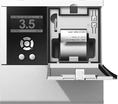
Operation and Display
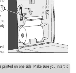
The screen displays instantaneous input readings. Use the arrow keys to toggle between display modes: Individual input information, Sequential input information, List of inputs, and Summary of inputs. Models with a printer (AKO-15742/15752/15782) allow for printing graphs and logs. To install the thermal paper roll, open the front cover, push the release lever, insert the paper, and feed it through the top slot.
Configuration
The programming menu allows for extensive customization:
- System Configuration: Set date/time, log intervals (5, 15, or 30 minutes), and alarm behavior.
- Input Configuration: Define the type of input (NTC, Pt100, Pt1000, 4-20mA, or Digital Input) and set alarm levels.
- Text Editor: Customize input names (up to 10 characters) and display units.
- Access Permits: Create up to 5 user profiles with 4-digit passwords to restrict configuration access.
Maintenance and Safety
Clean the surface of the device using a soft cloth, soap, and water. Avoid abrasive detergents, petrol, alcohol, or solvents. The device includes rechargeable accumulators that must be replaced when autonomy is low; use only the AKO-15704 part. Periodic checks should be performed in accordance with standard UNE EN 12830.
Manufacturer information
AKO Group
Practical help
Common problems
Probe error (Err)
Check if the probe is open, crossed, or off-scale. Ensure the correct probe type is configured in the input settings.
Access to configuration blocked
If a user enters the wrong password three times, access is blocked. Use the specific numerical key provided in the manual's table on page 10 to unblock.
Printer not working
Ensure the thermal paper is inserted correctly (thermal side up). Verify that at least one entry has been recorded.
Battery mode failure
Ensure the battery cable is connected to the panel connector. If autonomy is low, replace the battery with part AKO-15704.
Before use
- Connect the battery cable to the panel connector.
- Verify the power supply is 100-240 Vac.
- Ensure the probe type matches the connected sensor (NTC, Pt100, Pt1000, 4-20mA).
- Install the device in a location protected from water and vibrations.
- Assign a unique Modbus address if connecting to a network.
Specs in practice
- IP65 Protection
- Requires the gasket between the equipment and the panel cut-out to be correctly installed.
- Log interval
- Determines the time between data captures (5, 15, or 30 min). Affects storage capacity and printing duration.
Images and diagrams
- Page 3: Battery connection diagram showing the cable (1) and panel connector (2).
- Page 11: Mounting instructions for wall and panel configurations.
- Page 12: Wiring diagrams for supply, outputs, and various probe types.
- Page 13: Connectivity diagram for RS485 network and thermal paper installation.
Model compatibility
- Pt100 probes are only compatible with models AKO-1575x and AKO-1578x.
- Use only probes supplied by AKO to ensure proper operation.
- The device complies with UNE EN 12830 standards.

Manual page author
David Miller
Documentation analyst
Organizes user manual content into clear summaries, with attention to model details, product context, and everyday usability.