HVAC / Refrigeration Controllers
AKO 16526 V2 Temperature and Electronic Expansion Controller Wiring Guide
Quick wiring and configuration guide for the AKO 16526 V2 controller. Includes connection diagrams for probes, digital inputs, relays, and expansion valves, along with setup parameter dependencies.
Table of contents
Manual images
Click an image to enlargeImportant Information
This document serves as a wiring and connection guide for the AKO 16526 V2 Temperature and Electronic Expansion Controller. Please note that the specific function of each input and output, and consequently the required wiring, depends on the options selected during the initial setup wizard and the configuration of specific parameters. Always refer to the latest technical sheets on the manufacturer's website for updates.
Wiring and Connections
The controller supports various probes and digital inputs. Connections for probes S1 through S6, as well as digital inputs D1 through D3, must be configured according to parameters I10, I20, and I30.
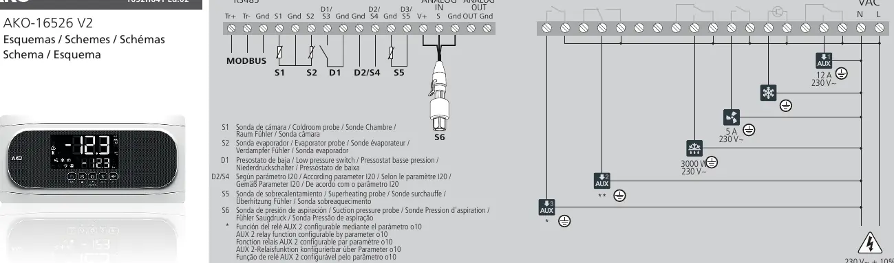
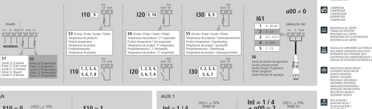
- Probes and Inputs: S1 (Coldroom), S2 (Evaporator), S3 (Product), S4 (Product/2nd Evaporator), S5 (Product/Superheating), S6 (Suction pressure).
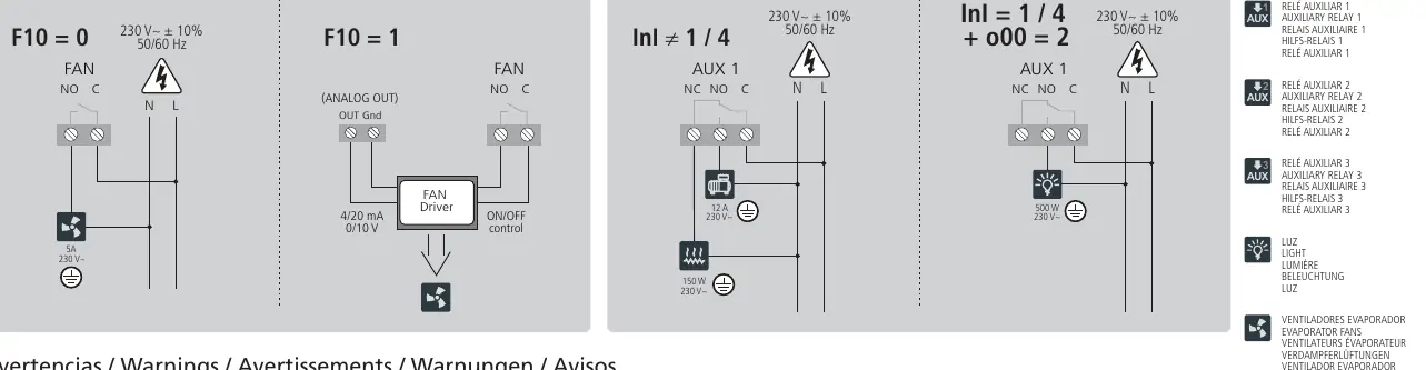
- Outputs: The device features multiple relay outputs (AUX 1, AUX 2, AUX 3), Fan control, Defrost, and Cool outputs.
- Analog Control: Analog output functionality (e.g., for EEV control) is determined by parameter u00 and F10 settings.
Warnings and Safety
The intensities and powers indicated in the diagrams are the maximum working values permitted. Always ensure that the connected loads do not exceed these limits. If your installation requires control of a STEPPER electronic expansion valve, refer to the specific application notes provided by AKO.
Manufacturer information
AKO Group
Practical help
Common problems
Incorrect input/output function
Verify the configuration in the setup wizard and check parameters I10, I20, I30, F10, and u00 to ensure they match your physical wiring.
Load exceeds limits
Ensure connected devices (fans, valves, heaters) do not exceed the maximum current/power ratings specified in the wiring diagrams.
Before use
- Verify power supply is 230V~ ± 10%, 50/60 Hz.
- Confirm all probe connections (S1-S6) match the intended application.
- Check that relay loads (AUX, Fan, Defrost, Cool) are within specified limits.
- Run the initial setup wizard to define input/output functions.
- Ensure the correct EEV control mode is set via parameter u00.
Images and diagrams
- The main diagram on page 1 shows the terminal layout for RS485, Modbus, Analog In/Out, and Relays.
- Page 2 details specific probe and digital input configurations based on parameters I10, I20, and I30.
- Page 2 illustrates Fan and AUX 1 wiring variations based on F10 and parameter settings.
Model compatibility
- Requires specific application notes for STEPPER electronic expansion valves.
- Functionality is software-dependent based on the initial setup wizard.

Manual page author
David Miller
Documentation analyst
Organizes user manual content into clear summaries, with attention to model details, product context, and everyday usability.