Lighting / Fixtures
User Manual for American Lighting RHYM-Series Recessed Downlight
Quick guide for the American Lighting RHYM-Series Recessed Downlight. Includes installation steps for new construction and remodels, wiring instructions, CCT selection, and maintenance tips.
Table of contents
Manual images
Click an image to enlargeQuick Guide from the Manual
The American Lighting RHYM-Series Recessed Downlight is designed for 120V AC, 60Hz electrical systems. It is suitable for dry, damp, or wet locations and is compatible with TRIAC, CL, and ELV dimming circuits. Always ensure power is turned off at the circuit breaker before beginning any installation or maintenance.
Pre-Installation Requirements
Before installing, determine the type of installation required:
- New Construction: An aluminum rough-in plate is available. Position the plate across two joists and secure it using hangar bars.
- Remodel: No mounting plate or can is required.
- Hole Cut Sizes: For both 3" Round and 3" Square models, the required cut-out size is 3-3/8" (86mm).
Installation Steps
Ensure power is turned off at the source before proceeding.
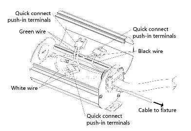
- Wiring: Open the hardwire box swing cover and remove the appropriate knockout. Insert the electrical supply cable and secure it with a cable connector.
- Connections: Using quick-connect push-in terminals, connect the green/ground wire to the green wire, the white wire to the white wire, and the black wire to the black wire in the junction box.
- Closing: Place all wiring back into the box, close the cover, and ensure no wires are pinched.
- Trim Installation: For trimless mud-ring, fasten the trim to the ceiling with screws, patch with drywall compound, and paint. For trim-ring, push up the butterfly springs to install the trim into the ceiling.
- Finalizing: Connect the light module to the driver using the twist-lock connector, turning clockwise to lock. Press the light module upwards into the trim until it clicks into place.
Adjustments and Lens Replacement
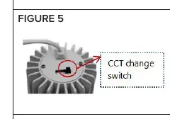
Color Temperature (CCT): Select the desired color temperature using the switch located on the backside of the light module.
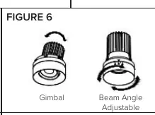
Gimbal and Beam Angle: If using the gimbal or beam angle adjustable module, set the desired angle and direction before final installation.
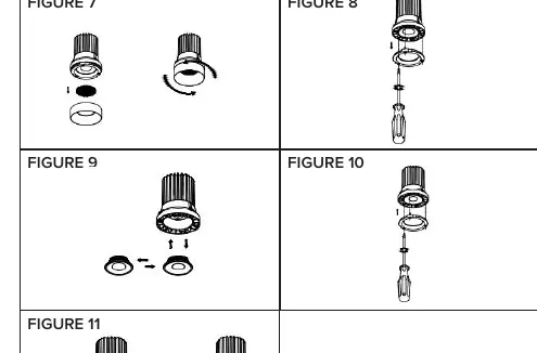
Optic Lens Replacement (THNC SKUs only):
- Remove the module ring by turning it counterclockwise.
- If using a honeycomb louver, remove it.
- Use a screwdriver to unscrew the inner ring screws.
- Change the lens, ensuring it is fully seated and facing the correct direction.
- Replace the inner ring, fasten screws, and reattach the module ring.
Care and Maintenance
Use only mild soap and water with a soft cloth to clean the fixture. Do not use harsh chemicals or rough cloths, as these may damage the finish or the lens.
Manufacturer information
American Lighting Inc.
Practical help
Common problems
Light module does not click into place
Ensure the trim is properly installed and the module is aligned correctly before applying upward pressure.
Lens replacement not possible
Optic lens replacement is only available for THNC SKUs; it is not applicable to gimbal or beam angle adjustable SKUs.
Wiring connections are loose
Ensure you are using the quick-connect push-in terminals correctly and that the cable is secured with a cable connector.
Before use
- Turn off power at the electrical panel.
- Verify power supply is 120V AC, 60Hz.
- Ensure supply conductors are rated for at least 90°C (194°F).
- Confirm the hole cut size is 3-3/8" (86mm).
- Check that the installation location is suitable (dry, damp, or wet).
Specs in practice
- Electrical Rating
- 120V AC, 60Hz.
- Hole Cut Size
- 3-3/8" (86mm) diameter for round or 3-3/8" x 3-3/8" for square.
Images and diagrams
- Figure 1 illustrates the wiring connections inside the hardwire box.
- Figure 5 shows the location of the CCT switch on the back of the light module.
- Figure 6 demonstrates the adjustment points for gimbal and beam angle models.
Model compatibility
- THNC SKUs support optic lens replacement.
- Gimbal and beam angle adjustable SKUs do not support optic lens replacement.

Manual page author
Emily Carter
User documentation editor
Prepares concise manual descriptions and highlights the most useful setup, operation, and maintenance information for readers.