Lighting / LED Strips
Installation Guide for American Lighting Trulux Static White IP54 LED Tape Light
Quick installation guide for American Lighting Trulux Static White IP54 LED Tape Light. Includes safety warnings, layout considerations, cutting instructions, and wiring connection steps.
Table of contents
Manual images
Click an image to enlargeQuick Guide
This guide covers the installation of the American Lighting Trulux Static White (IP54) LED Tape Light series. Always ensure the electrical power is disconnected at the source before beginning any installation or servicing. This product is intended for indoor use in dry and damp locations only and must be powered by a 24V DC driver.
Product Information
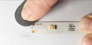
The IP54 rated tape light features a protective nano-coating. Important: It is recommended to scrape off this coating from each conductor to ensure a proper electrical connection. The tape light uses 3M VHB adhesive on the back; once applied, it should not be repositioned or reused.
Layout Considerations
Pay close attention to the maximum run lengths for your specific series to avoid performance issues. Do not load a driver to 100% capacity; a 90% maximum load is recommended for efficiency.
- STL Series: 32.8 feet max run
- STLHD Series: 32.8 feet max run
- STL-COB Series: 23 feet max run
- HTL Series: 22 feet max run
- HTLHD Series: 27 feet max run
- HTL-COB Series: 16.4 feet max run
- SPTLECO Series: 16.4 feet max run
- SPTL Series: 13.1 feet max run
- SPTLX Series: 13.1 feet max run
- SPTL-SCOB Series: 16.4 feet max run
- VTL Series: 13.1 feet max run
Installation Instructions
Cutting the Tape: Cut increments are clearly marked on the tape. Cut down the center of the copper conductor pads to ensure enough surface area is exposed for the snap connector pins.
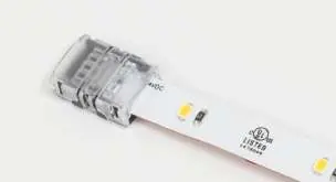
Making a Tape-to-Tape Connection:
- Ensure the polarity of the conductors on both pieces of tape light are aligned.
- Open both sides of the tape-to-tape snap connector to expose the metal teeth.
- Peel a small portion of the protective backing from the tape light end.
- Insert the cut tape light end so the copper pad conductors align with the metal teeth.
- Close the snap connector and use pliers to ensure it snaps through the tape light.
Making a Tape-to-Wire Connection:
- Follow the steps for the tape-to-tape connection to prepare the tape light.
- Ensure the polarity of the tape light conductors and the wires align.
- Cut the desired length of wire, leaving approximately 1/2 inch on each end.
- Separate the wires slightly to fit into the grooves of the snap connector (no need to strip the wire).
- Insert the wire into the slots of the snap connector, ensuring alignment with the metal teeth.
- Close the snap connector and use pliers to ensure it snaps through the wire.
Safety and Warranty
Never fold the tape light or bend it past the minimum bending radius of 1 inch. Do not install in airtight tanks or enclosures. For technical assistance or repair parts, call 1-800-285-8051 (M-F 8am – 5pm, MST). The product includes a 5-year limited warranty against defects in material and workmanship.
Manufacturer information
American Lighting Inc.
Practical help
Common problems
Tape light not lighting up
Check polarity of conductors, ensure snap connector is fully closed, and verify 24V DC driver is connected.
Connection failure
Ensure the nano-coating is scraped off the conductors to expose the copper pads before inserting into the connector.
Voltage drop or dimming
Ensure you are not exceeding the maximum run length for your specific series.
Before use
- Verify 24V DC driver is compatible with the total load.
- Ensure electrical power is disconnected at the source.
- Check that the installation location is dry or damp (IP54 rated, not for direct water contact).
- Confirm you have the correct snap connectors (TL-BLKS, TL-CONKIT, TL-2PWR-HD).
- Prepare mounting surface (clean and dry).
Specs in practice
- Cut Increments
- Specific intervals where the tape can be safely cut to length.
Images and diagrams
- Figures 2-5: Steps for cutting the tape and making a tape-to-tape connection using snap connectors.
- Figures 6-9: Steps for connecting the tape light to wire using snap connectors.
Model compatibility
- Use only with 24V DC drivers.
- Do not use with non-recommended power supplies to avoid voiding the warranty.
- Not for use in airtight tanks or enclosures.

Manual page author
David Miller
Documentation analyst
Organizes user manual content into clear summaries, with attention to model details, product context, and everyday usability.