Computers / Laptops
Teardown guide for MacBook Pro 16-inch 2019
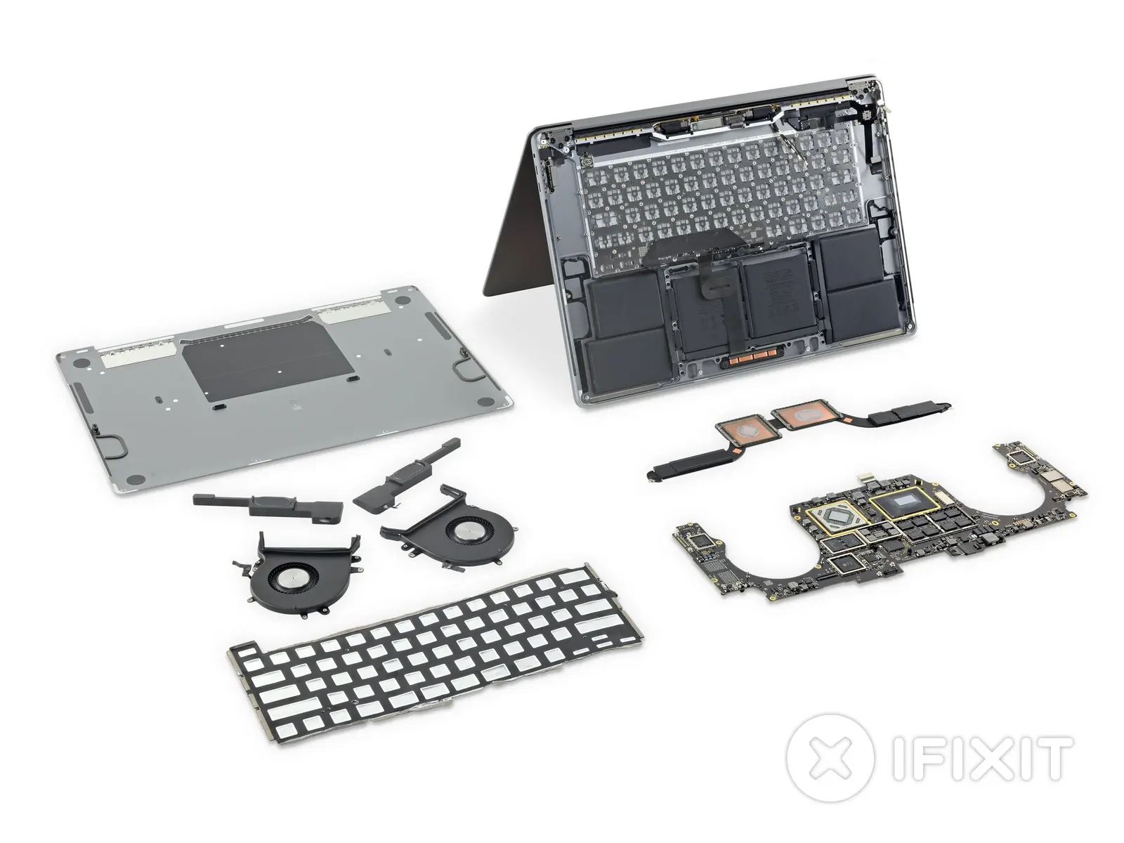
A comprehensive teardown guide for the 2019 16-inch MacBook Pro (Model A2141). This guide details the internal components, including the logic board, battery, and keyboard mechanism, along with a repairability assessment.
Table of contents
Manual images
Click an image to enlargeQuick guide from the manual
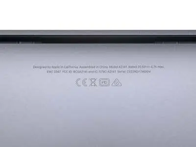
This document provides a detailed teardown of the 2019 16-inch MacBook Pro (Model A2141, EMC 3347). It highlights the internal layout, component identification, and repairability challenges. The device features a 16-inch Retina display (3072 x 1920), Intel Core i7 processor, 16GB RAM, 512GB SSD, and a 100Wh battery.
Tools required
- Spudger
- Suction Handle
- iFixit Opening Picks (set of 6)
- Tweezers
- T5 Torx Screwdriver
- T3 Torx Screwdriver
- T8 Torx Screwdriver
- P2 Pentalobe Screwdriver
Keyboard analysis
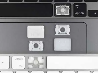
The 2019 model features a redesigned Magic Keyboard with a scissor switch mechanism. Unlike previous butterfly keyboards, this design does not include a dust membrane. While the keycaps are removable, the keyboard assembly itself is riveted to the chassis, making it difficult to repair or replace.
Internal components
The teardown reveals several key internal upgrades:
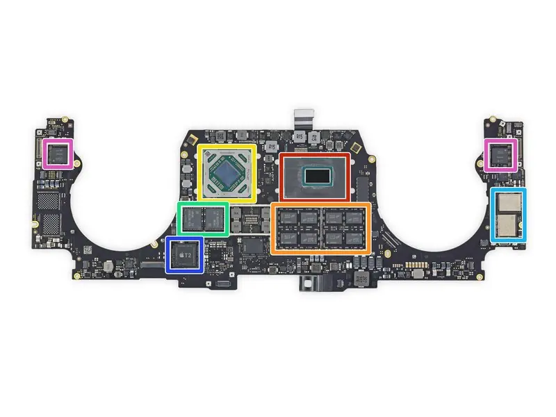
- Logic Board: Contains the 9th Gen Intel Core i7 processor, Micron DDR4 SDRAM, AMD Radeon Pro 5300M GPU, Samsung GDDR6 RAM, Toshiba flash storage, Apple T2 coprocessor, and Intel Thunderbolt 3 controller.
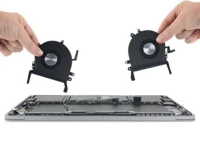
- Cooling System: Features larger fans and a redesigned heatsink that allows for 28% more airflow and higher power dissipation.
- Battery: A 100Wh (11.36 V, 8790 mAh) battery, which is the largest capacity seen in a MacBook, designed to meet FAA limits.
- Sensors: A new lid angle sensor is integrated into the left hinge, requiring calibration after repairs.
Repairability assessment
The MacBook Pro 16-inch 2019 receives a repairability score of 1 out of 10. While the trackpad is relatively easy to replace, most other components are highly integrated. The processor, RAM, and flash storage are soldered to the logic board. The keyboard, battery, and speakers are secured with glue or rivets, significantly increasing the complexity of repairs.
Manufacturer information
Apple Inc.
Practical help
Common problems
Keyboard repair
The keyboard assembly is riveted to the chassis, making it extremely difficult to replace.
Component upgrades
The processor, RAM, and flash storage are soldered to the logic board and cannot be upgraded.
Battery replacement
The battery is glued into the chassis, making removal and replacement very difficult.
Before use
- Ensure you have the correct tools: Spudger, Suction Handle, iFixit Opening Picks, Tweezers, T5, T3, T8 Torx, and P2 Pentalobe screwdrivers.
- Power off the device completely before starting any disassembly.
- Handle the 100Wh battery with extreme caution to avoid puncture or damage.
- Note that the lid angle sensor in the left hinge may require calibration after display removal.
Specs in practice
- 100 Wh battery
- The maximum capacity allowed for air travel.
- 3072 x 1920 resolution
- 16-inch Retina display with 226 ppi.
Images and diagrams
- The logic board layout identifies the CPU, GPU, RAM, and T2 security chip.
- The keyboard mechanism diagram shows the scissor switch structure.
- The fan assembly diagram illustrates the improved airflow design.
Model compatibility
- The keyboard is not interchangeable with older Magic Keyboards due to differences in keycap thickness and backlight design.

Manual page author
Michael Turner
Technical manual editor
Reviews PDF manuals for structure, safety notes, and practical product details so readers can find the right information quickly.