Home Appliances / Dehumidifiers
Troubleshooting Manual for Aprilaire 1710A, 1750A, 1770A Dehumidifier
A comprehensive troubleshooting guide for Aprilaire 1710A, 1750A, and 1770A dehumidifiers. Includes detailed fault code analysis, capacity verification procedures, water leak resolution, and electrical schematics.
Table of contents
Manual images
Click an image to enlargeQuick guide from the manual
This manual provides troubleshooting procedures for Aprilaire dehumidifier models 1710A, 1750A, and 1770A. Before beginning, ensure you have the necessary tools: a Digital Multi-Meter (DMM) capable of measuring AC/DC voltage, resistance, and capacitance; a temperature meter; a humidity meter; a #2 Phillips screwdriver; a small flat head screwdriver; needle nose pliers; and a level.
Important Safety Warning: Do not connect refrigeration gauges to the dehumidifier, as this will result in refrigerant loss and performance degradation.
Troubleshooting Fault Codes
The red Fault LED on the control board blinks to indicate specific issues. Count the number of blinks to identify the fault:
- 1 blink: Control board is not receiving a signal from the thermistor. Inspect sensor arm pins and the control board socket.
- 2 blinks: Control board is not receiving a signal from the RH sensor. Inspect sensor arm pins and the control board socket.
- 3 blinks: Communication loss with Model 70 or 76 control. Verify wiring connections at the A, B, +, and - terminals.
- 4 blinks: Frost sensor indicates the suction line temperature has not dropped sufficiently. This suggests the compressor is not running or the refrigeration system is failing.
- 5 blinks: Incoming air temperature is outside the operating range (below 50°F or above 100°F).
- 6 blinks: Frost sensor signal is out of range (-20°F to 150°F). Check connections or replace the sensor.
- 7 blinks: Float switch input is open. Check for water in the secondary drain pan or a faulty float switch.
Verifying Capacity
If the unit is running but not removing sufficient moisture, follow these steps:
- Ensure the flap damper on the outlet opens and closes freely.
- Verify ductwork is free of obstructions and the filter is clean.
- Ensure all panels are secured with screws.
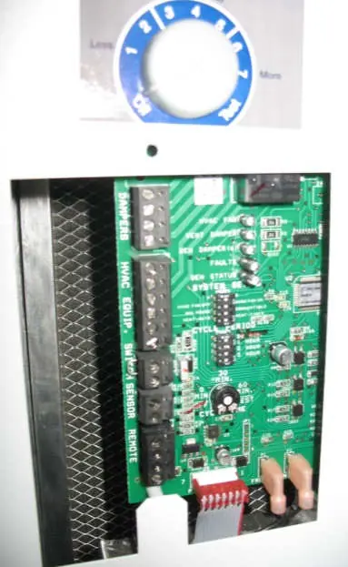
- Disconnect HVAC equipment and remote controls from the terminal blocks.
- Set the system switch to LOCAL and the control knob to the highest setting (7).
- Measure inlet air temperature and RH, then compare with discharge air conditions using the provided performance graphs.
Water Leaks
Water should collect in the drain pan and exit through the drain tube. If leaks occur:
- Ensure the unit is level side-to-side.
- Clean the drain trap and tubing.
- Ensure there are no upward bends in the drain line, which can cause air-locks.
- Verify the custom running trap provided with the unit is used; do not use standard traps.
Blower and Electrical Issues
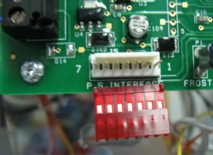
If the blower does not function, verify 120 VAC power is available. Inspect the power board for scorched components (varistors). If the fan LED is lit but there is 0 VAC at the fan terminals, check the ribbon cable and control board connections. For circuit breaker trips, ensure the unit is on a dedicated circuit (15A for 1710A/1750A, 20A for 1770A) and check the compressor run capacitor.
Manufacturer information
AprilAire
Practical help
Common problems
4 blinks (Frost Sensor fault)
Compressor is not running or refrigeration system is failing. Check compressor wiring, run capacitor, and high temperature switch.
Water leaks
Check for clogs in the drain trap/tubing and ensure there are no upward bends in the drain line causing air-locks.
Circuit breaker trips
Verify the circuit is not overloaded. 1710A/1750A requires 15A; 1770A requires 20A. Check for faulty compressor run capacitor.
Blower does not function
Check for 120 VAC at the outlet. Inspect power board for scorched varistors. If fan LED is lit but no voltage at terminals, check ribbon cable.
Before use
- Digital Multi-Meter (DMM) for voltage, resistance, and capacitance
- Temperature meter
- Humidity meter
- Phillips screwdriver (#2)
- Small flat head screwdriver
- Needle nose pliers
Specs in practice
- Run Capacitor (1710A/1750A)
- 55 microfarads ± 5%
- Run Capacitor (1770A)
- 60 microfarads ± 5%
- 1710A/1750A Circuit Breaker
- 15 amp
- 1770A Circuit Breaker
- 20 amp
Images and diagrams
- Wiring schematics for 1750A and 1770A are provided to assist in identifying terminal connections for the blower, compressor, and control boards.
Model compatibility
- Do not use refrigeration gauges; it causes refrigerant loss.
- 1770A requires a 20 amp circuit.
- Use only the provided custom running trap.

Manual page author
Michael Turner
Technical manual editor
Reviews PDF manuals for structure, safety notes, and practical product details so readers can find the right information quickly.