Computers / Desktop Computers
User Manual for ASRock NUC-1360P/D4 Motherboard
Comprehensive user manual for the ASRock NUC-1360P/D4 motherboard. This guide provides detailed instructions on hardware installation, memory and storage configuration, I/O panel connectivity, and UEFI BIOS setup.
Table of contents
Manual images
Click an image to enlargeQuick Start Guide
The ASRock NUC-1360P/D4 is a compact motherboard designed for Intel 13th Gen Raptor Lake-P processors. Before beginning installation, ensure you have a compatible chassis and power supply. Always unplug the power cord before touching any internal components to prevent electrical damage. Use a grounded wrist strap or touch a grounded object to discharge static electricity before handling the motherboard.
Hardware Installation
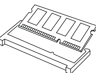
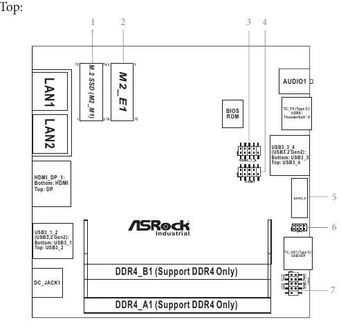
Memory Installation: The motherboard features two 260-pin SO-DIMM slots supporting dual-channel DDR4 3200 MHz memory. Align the notch on the SO-DIMM module with the break in the slot and press firmly until the retaining clips snap into place.
Expansion Slots: The board includes two M.2 sockets. The M.2 Key-M socket supports PCIe Gen4 x4 for SSDs (2242/2260/2280). The M.2 Key-E socket is intended for Wi-Fi modules (2230).
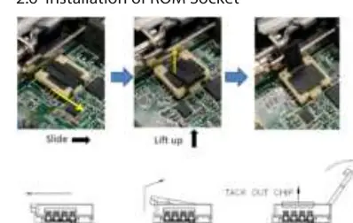
ROM Socket: When installing the ROM chip, ensure the yellow dot (Pin 1) is aligned with the Pin 1 position on the socket. Do not apply excessive force to the actuator cover.
Motherboard Layout and Connectors
The motherboard features various headers for system integration:
- System Panel Header (PANEL1): Connects the power switch, reset switch, and system status LEDs.
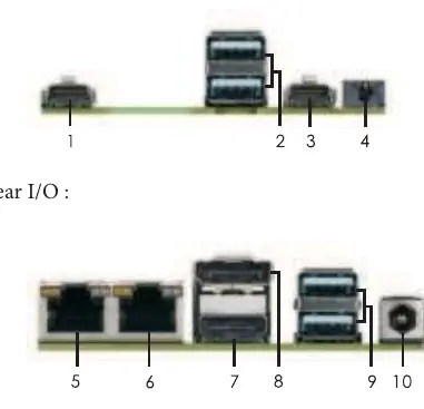
- USB Headers: Includes internal USB 2.0 headers and various rear I/O USB 3.2 Gen2 and USB4/Thunderbolt 4 ports.
- COM Port Header: Supports RS-232/422/485 configurations, adjustable in the BIOS.
- SATA3 Port: Provides 6.0 Gb/s data transfer for internal storage.
- JP1 Header: Used for SIO AT/ATX mode selection and clearing CMOS.
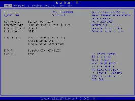
UEFI BIOS Setup
To enter the UEFI Setup Utility, press the F2 or Delete key immediately after powering on the computer. The BIOS allows for advanced configuration of CPU settings, chipset parameters, storage modes (AHCI), and security features like TPM 2.0.
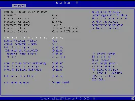
Key BIOS Sections:
- CPU Configuration: Manage Hyper-Threading, P-Core/E-Core settings, and C-States.
- Chipset Configuration: Adjust VT-d, Re-Size BAR support, and shared memory for integrated graphics.
- Hardware Health: Monitor CPU/motherboard temperatures and fan speeds.
- Security: Set supervisor/user passwords and configure Secure Boot.
Safety and Maintenance
This product contains a button battery (CR2032). Keep batteries out of reach of children. If swallowed, seek immediate medical attention. Do not attempt to recharge, disassemble, or incinerate the battery. Dispose of electronic components according to local environmental regulations.
Practical help
Common problems
System fails to boot or becomes unstable
Clear the CMOS using the JP1 header or reset BIOS settings to default values.
BIOS settings are not saved
Check the battery connection (BAT1) or replace the CR2032 battery.
Memory not detected
Ensure SO-DIMM modules are fully seated and that you are not mixing different voltage modules.
Before use
- Unplug the power cord from the wall socket before touching any component.
- Use a grounded wrist strap or touch a grounded object to prevent static damage.
- Hold components by the edges and avoid touching ICs.
- Verify that the chassis configuration is compatible with the NUC form factor.
- Ensure the power supply is switched off before installation.
Specs in practice
- DDR4 3200 MHz
- Supported memory speed for dual-channel configuration.
- USB4/Thunderbolt 4
- High-speed port supporting data transfer and display output.
Images and diagrams
- Motherboard Layout: Identifies locations of M.2 slots, SATA ports, and system headers.
- I/O Panel: Shows the arrangement of rear ports including LAN, HDMI, and USB.
- Block Diagram: Illustrates the data path between the CPU, chipset, and peripherals.
Model compatibility
- Supports Intel 13th Gen Raptor Lake-P processors.
- Memory capacity up to 64GB (32GB per DIMM).
- SATA3 interface supports up to 6.0 Gb/s.

Manual page author
David Miller
Documentation analyst
Organizes user manual content into clear summaries, with attention to model details, product context, and everyday usability.