Computers / PC Components
Installation Guide for Gigabyte GC-MAPLE RIDGE Add-in Card
Quick installation guide for the Gigabyte GC-MAPLE RIDGE Thunderbolt 4 add-in card. Includes step-by-step connection instructions for PCIe, USB, and Thunderbolt headers, as well as daisy-chaining setup and driver installation.
Table of contents
Manual images
Click an image to enlargeQuick Guide
The GC-MAPLE RIDGE is a Thunderbolt 4 add-in card designed to provide high-speed data transfer and display output capabilities. This guide covers the physical installation, internal cable connections, and driver setup required to operate the card.
Product Specifications
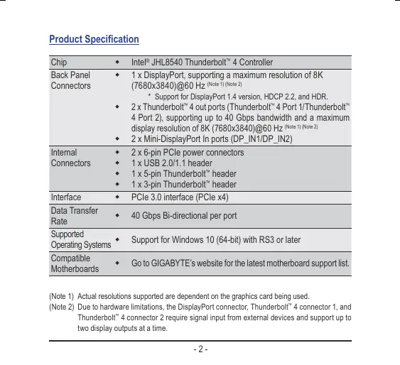
- Chip: Intel JHL8540 Thunderbolt 4 Controller
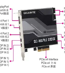
- Back Panel Connectors: 1 x DisplayPort (up to 8K@60Hz), 2 x Thunderbolt 4 ports (up to 40 Gbps), 2 x Mini-DisplayPort In ports
- Internal Connectors: 2 x 6-pin PCIe power connectors, 1 x USB 2.0/1.1 header, 1 x 5-pin Thunderbolt header, 1 x 3-pin Thunderbolt header
- Interface: PCIe 3.0 (PCIe x4)
- Supported OS: Windows 10 (64-bit) RS3 or later
Installation Steps
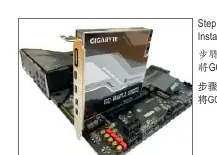
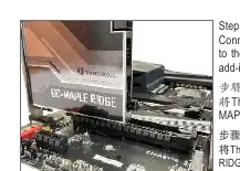
- PCIe Installation: Insert the GC-MAPLE RIDGE card into an available PCIEX4 slot on your motherboard.
- USB Connection: Connect one end of the provided USB cable to the USB connector on the card and the other end to the F_USB header on the motherboard.
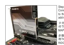
- Thunderbolt Headers: Connect the 5-pin Thunderbolt header cable to the card and the corresponding Thunderbolt add-in card header on the motherboard. Repeat this process for the 3-pin Thunderbolt header if supported by your motherboard.
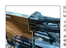
- Power Connection: Connect the power cables from your power supply unit to the two 6-pin PCIe power connectors on the card.
- Display Setup: Use the included Mini-DisplayPort cables to connect the DisplayPort output on your graphics card to the Mini-DisplayPort In connectors on the GC-MAPLE RIDGE card.
Daisy-chaining Thunderbolt Devices
To daisy-chain Thunderbolt-enabled devices, ensure that all devices in the chain have both Thunderbolt In and Out ports. Connect the devices in a series configuration starting from the Thunderbolt 4 port on the GC-MAPLE RIDGE card.
Driver Installation
After installing the hardware and starting your computer, insert the included driver disc and follow the on-screen instructions to install the necessary drivers. For the latest software, visit the GIGABYTE website and navigate to the Support & Downloads section.
Contact Information
For technical and non-technical support, visit https://esupport.gigabyte.com. For product information, visit https://www.gigabyte.com.
Official resources from the manual
Manufacturer information
Gigabyte Technology Co., Ltd.
Practical help
Common problems
Display not working
Ensure the Mini-DisplayPort cables are correctly connected between your graphics card's DisplayPort output and the GC-MAPLE RIDGE's Mini-DisplayPort In inputs.
Thunderbolt device not detected
Verify that the motherboard BIOS is updated to the latest version and that all internal headers (USB, 5-pin, and 3-pin Thunderbolt) are securely connected.
Before use
- Ensure your motherboard is compatible with the GC-MAPLE RIDGE card.
- Update your motherboard BIOS to the latest version.
- Have a graphics card with an available DisplayPort output.
- Ensure your power supply has two available 6-pin PCIe power connectors.
- Verify you have the included cables: Mini-DisplayPort, USB header, and Thunderbolt header cables.
Specs in practice
- Thunderbolt 4
- Provides up to 40 Gbps bi-directional bandwidth and supports 8K display resolution.
- Mini-DisplayPort In
- Inputs required to pass the video signal from your dedicated graphics card to the Thunderbolt ports.
Images and diagrams
- The card features two Mini-DisplayPort In ports (DP_IN1/DP_IN2) which must be connected to the graphics card.
- Internal headers include a USB 2.0 header, a 5-pin Thunderbolt header, and a 3-pin Thunderbolt header.
- The card requires two 6-pin PCIe power connectors to operate.
Model compatibility
- Requires Windows 10 (64-bit) with RS3 or later.
- Actual supported resolutions depend on the graphics card being used.
- The DisplayPort connector and Thunderbolt 4 ports require signal input from external devices.

Manual page author
Michael Turner
Technical manual editor
Reviews PDF manuals for structure, safety notes, and practical product details so readers can find the right information quickly.