Tools / Automotive Tools
Owner's Manual for ATD 6558 2-In-1 Masking Film Dispenser
Quick guide for the ATD 6558 2-In-1 Masking Film Dispenser. Includes step-by-step assembly instructions, a comprehensive parts list, and warranty information.
Quick answers from the manual
Quick answer
- The ATD 6558 is a 2-in-1 masking film dispenser. It is assembled using a series of bolts and braces, with a film cutter bar and roll bar for holding and dispensing masking film. p. 1, 2
Key actions
- Assemble the unit by attaching the wheels, braces, poles, and film cutter bar according to the 11-step assembly instructions. p. 2
First start
- Unpack components, verify against parts list, assemble the frame, attach the film cutter bar, and load the masking film roll. p. 2
Technical specifications
| Parameter | Value | Meaning | Pages |
|---|---|---|---|
| Assembled Dimensions | 50" x 23.6" x 28.3" | Overall size of the assembled unit | p. 1 |
Where to find it in the PDF
- Product Overview and Features p. 1
- Assembly Instructions p. 2
- Assembly Diagrams p. 3, 4
- Replacement Parts List p. 5
- Warranty Information p. 6
Table of contents
Manual images
Click an image to enlargeQuick guide from the manual
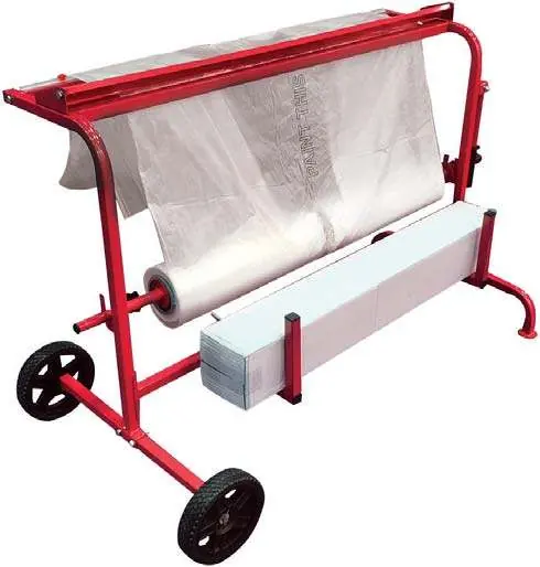
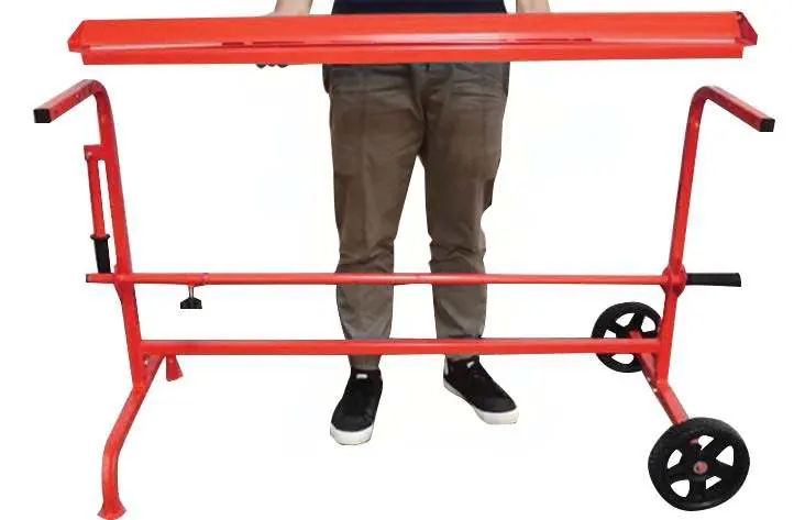
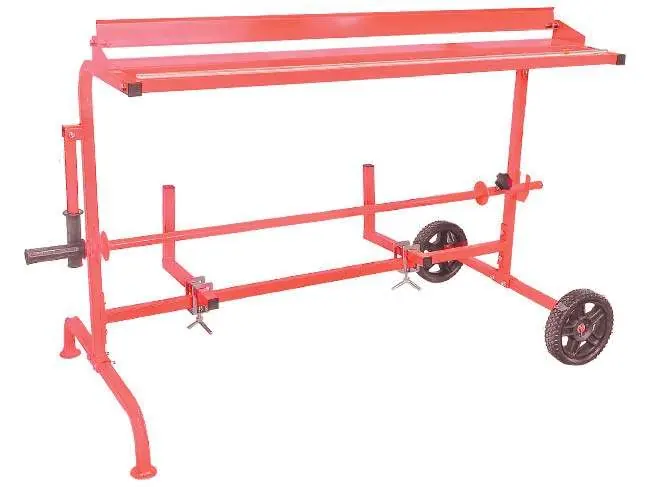
The ATD 6558 is a 2-in-1 masking film dispenser designed for one-person operation. It is built with a powder-coated finish for corrosion resistance and features large diameter wheels for easy maneuverability. The unit accommodates standard film rolls with a maximum width of 47.2 inches and a maximum diameter of 11.8 inches.
Assembly Instructions
Follow these steps to assemble your dispenser:
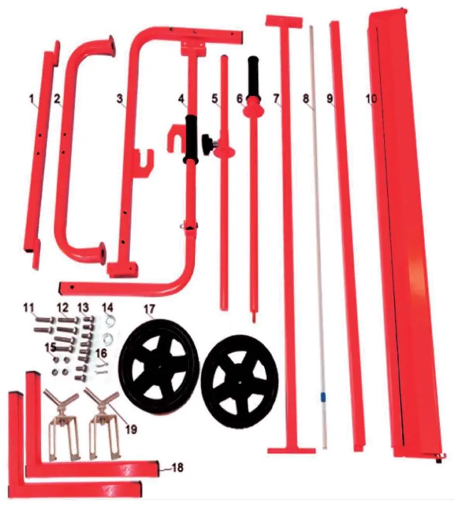
- Unpack all components and compare them with the parts list to ensure nothing is missing.
- Attach the wheels (17) to the wheel pole (1) using the flat washer (14) and cotter pins (16).
- Assemble the rear brace (3) to the wheel assembly using bolts (12 & 15). Attach the front brace (4) to the front pole using the same bolts.
- Connect the bottom pole (7) between the front and rear brace assemblies using bolts (13).
- Attach the film roll bar (5) with the handle (6) and position it between the brace assemblies.
- Install the film dispenser platform (10) between the front and rear braces using bolts (13).
- Attach the square bar (9) between the front and rear braces using bolts (11).
- Secure the L square tubes (18) to the bottom pole (7) using the buckles with knobs (19). Tighten firmly.
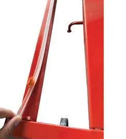
- Attach the film cutter bar (8) to the square bar (9) using the adhesive on the back of the cutter.
- Load your masking film onto the film roll bar (05 & 06).
- Route the film through the dispenser as shown in the manual diagrams.
Replacement Parts
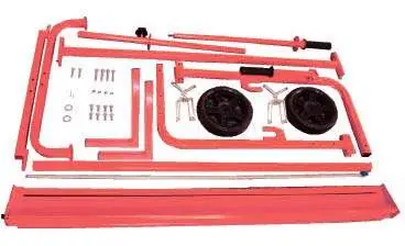
The manual includes a detailed parts diagram and a table listing all components (1-19). When ordering replacement parts, refer to the Item# and Ordering Part# provided in the table. Ensure you have the model number (ATD-6558) ready when contacting your distributor for pricing.
Warranty
This product comes with a 1-year limited warranty from the date of purchase. ATD Tools, Inc. will repair or replace the product if it fails due to defects in material or workmanship under normal use. Retain your receipt or invoice at all times for warranty claims.
Practical help
Common problems
Missing components during assembly
Compare all parts against the included parts list immediately upon unpacking. Contact your point of purchase if any pieces are missing.
Film not cutting smoothly
Ensure the film cutter bar is correctly aligned and attached to the square bar. Verify that the film is routed properly through the dispenser.
Before use
- Unpack all components carefully.
- Verify all parts against the parts list.
- Ensure all bolts and hardware are tightened securely.
- Check that the film roll meets the size requirements (max width 47.2", max diameter 11.8").
Specs in practice
- Assembled Size
- 50" x 23.6" x 28.3"
- Max Film Width
- 47.2 inches
- Max Film Diameter
- 11.8 inches
Images and diagrams
- Figure 1: Exploded view of all components.
- Figures 2-9: Step-by-step visual guide for assembly.
- Figure 10: Final assembled unit with film installed.
Model compatibility
- Designed for standard masking film rolls.
- Not suitable for rolls exceeding 47.2" in width or 11.8" in diameter.

Manual page author
David Miller
Documentation analyst
Organizes user manual content into clear summaries, with attention to model details, product context, and everyday usability.