Industrial / Electrical
User Manual for Auraton Switch TWO 2-Channel Smart Relay Module
Comprehensive user guide for the Auraton Switch TWO 2-channel smart relay module. Includes installation instructions, wiring diagrams, technical specifications, and operating procedures.
Quick answers from the manual
Quick answer
- The Auraton Switch TWO is a 2-channel smart relay module that allows remote control of electrical devices via radio (using AURATON Box) or local control via a button. It supports 12-30V DC or 60-240V AC power. p. 1
Key actions
- Pairing with AURATON Box p. 1
Technical specifications
| Parameter | Value | Meaning | Pages |
|---|---|---|---|
| Power Supply | 60-240V AC or 12-30V DC | Input voltage range | p. 2 |
| Max Load | 4.3A (<1kW) per channel | Maximum resistive load | p. 2 |
Where to find it in the PDF
- Device Overview and Wiring p. 1
- Technical Data p. 2
Table of contents
Manual images
Click an image to enlargeImportant Information
The Auraton Switch TWO is a 2-channel executive module designed to control electrical devices. It supports both 12-30V DC and 60-240V AC power sources. Important: The device must be installed in an installation box with a minimum depth of 60 mm.
Device Description
The device features three main components:
- Connection terminals: For power and load wiring.
- Signaling diode: Indicates device status.
- Button: Used for pairing the device with the system or removing it.
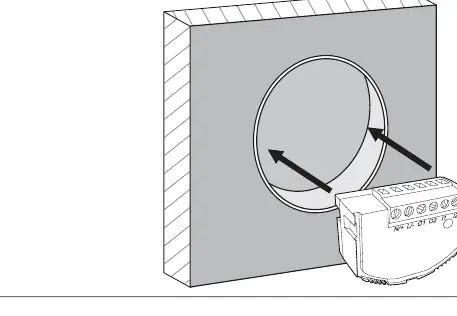
Installation
The device is designed for flush mounting. Ensure the installation box meets the minimum depth requirement of 60 mm to accommodate the module and wiring.
Wiring Diagram
The device supports both AC and DC power. Follow the connection guidelines carefully:
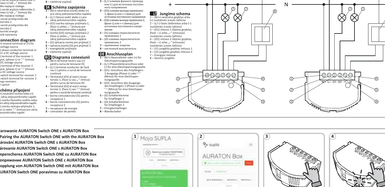
- Terminals 1 & 2: Power input. Use (N/+) and (L/-) for AC, or (+) and (-) for DC.
- Terminals 3 & 4 (O1, O2): Outputs for receivers.
- Terminals 5 & 6 (l1, l2): Inputs for wall switches to control receiver 1 and receiver 2 respectively.
- Terminals 7 & 8: Represent the energy receivers and the wall switch connection points.
Operation
The device can be controlled in two ways:
- Remotely: Via radio communication when paired with an AURATON Box.
- Locally: By pressing the button on the device or using a connected wall switch.
Technical Specifications
- Power Supply: 60-240 V AC (50-60 Hz) or 12-30 V DC.
- Max Load: Up to 4.3 A (
- Radio Frequency: 868.150 MHz; 868.450 MHz.
- Operating Temperature: 0 – 35°C.
- Protection Rating: IP20.
Disposal
The device is marked with a crossed-out waste bin symbol, indicating it must not be disposed of with household waste. Users are responsible for delivering the device to a designated collection point for electrical and electronic equipment.
Practical help
Common problems
Device not responding to commands
Ensure the device is correctly paired with the AURATON Box and check the power supply connections.
Installation box too shallow
The device requires a minimum installation box depth of 60 mm. If your box is shallower, you may need to replace it.
Before use
- Verify that your power source is either 12-30V DC or 60-240V AC.
- Ensure the installation box has a minimum depth of 60 mm.
- Check that the load does not exceed 4.3A per channel.
- Confirm the device is within the 30m operating range of the AURATON Box.
Specs in practice
- Resistive load
- The maximum current of 4.3A applies specifically to resistive loads (e.g., heaters, incandescent bulbs).
Images and diagrams
- The wiring diagram illustrates connections for both AC and DC power sources.
- Terminals 1 and 2 are for power input.
- Terminals 3 and 4 (O1, O2) are for receiver outputs.
- Terminals 5 and 6 (l1, l2) are for wall switch inputs.
Model compatibility
- Compatible with AURATON Box for remote control.
- Uses AURA radio protocol.

Manual page author
Emily Carter
User documentation editor
Prepares concise manual descriptions and highlights the most useful setup, operation, and maintenance information for readers.