Smart Home / Smart Relays
Operating instructions for GIRA 5062 Switching Actuator
Quick guide for the GIRA 5062 Switching Actuator. Learn about installation, wiring, KNX commissioning, safe-state mode, and technical specifications.
Quick answers from the manual
Quick answer
- The GIRA 5062 is a KNX switching and blind actuator with 3 binary inputs. It is installed in appliance boxes and configured via ETS software. p. 2, 3
Key actions
- Commissioning p. 6
- Master Reset p. 7
First start
- Connect KNX bus, wait 10s, then connect load circuit. p. 6
Problems and fixes
Safe-state mode active
Switch off bus voltage (wait approx. 10 s) or carry out ETS programming to deactivate.
p. 6, 7Maintenance and reset
- Master reset restores basic device settings. p. 7
Technical specifications
| Parameter | Value | Meaning | Pages |
|---|---|---|---|
| Switching voltage | AC 250 V | Maximum switching voltage | p. 7 |
| Switching current | 16 A | Maximum switching current per device | p. 7 |
| Dimensions | 48 x 50 x 28 mm | Physical size | p. 7 |
Where to find it in the PDF
- Safety instructions p. 1
- Installation and connection p. 4, 5
- Commissioning p. 6
- Technical data p. 7, 8
Table of contents
Manual images
Click an image to enlargeQuick guide from the manual
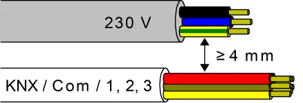
The GIRA 5062 is a KNX-based switching and blind actuator with three binary inputs. It is designed for installation in appliance boxes and requires configuration via the ETS software. Important: Installation must be performed by electrically skilled persons. Ensure a minimum distance of 4 mm between mains voltage and bus/extension wires to prevent electric shock and damage to the KNX installation.
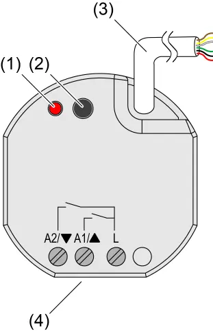
Device components
The device features a programming LED and button for configuration, a control cable for KNX and extension inputs, and screw terminals for load connection.
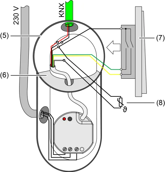
Installation and electrical connection
For safe operation, use an appliance box with a fixed partition wall to separate the KNX bus/extensions from the mains voltage. Warning: Do not place bus/extensions and mains voltage terminals in a shared connection compartment without a partition.
- Connect the device to the KNX bus with the correct polarity.
- Connect the load circuit to the relay outputs.
- Connect potential-free contacts, dew/leakage sensors, or NTC temperature sensors (to input 3) as required.
- Ensure adequate cooling and observe ambient temperature limits.
Commissioning
Commissioning is performed using the ETS software (version 5.7.3 or higher). Before switching on the load, ensure all relay contacts are open by applying the KNX bus voltage first.
- Standard Commissioning: Switch on KNX bus voltage, wait 10 seconds, then connect the load circuit.
- Safe-state mode: Used to stop the application program. To activate, switch off bus voltage, wait 10 seconds, press and hold the programming button, then switch on bus voltage. Release the button when the programming LED flashes slowly.
- Master reset: Restores basic device settings. Activate safe-state mode, then press and hold the programming button for more than 5 seconds until the LED flashes quickly.
Technical data
The device operates on the KNX TP256 medium with a rated voltage of DC 21-32 V. It supports switching currents up to 16 A. Ambient temperature range is -5 to +45 °C. Dimensions are 48 x 50 x 28 mm.
Practical help
Common problems
Device not responding or behaving unexpectedly
Check KNX bus voltage and polarity. Ensure the device is not in safe-state mode.
Incorrect load control
Ensure relay contacts are open before switching on the load during commissioning.
Programming LED flashing
The device may be in safe-state mode or programming mode. Check the status via ETS.
Before use
- Ensure installation is performed by an electrically skilled person.
- Verify the appliance box has a fixed partition wall.
- Ensure a minimum distance of 4 mm between mains voltage and bus/extension wires.
- Check that KNX bus voltage is switched off before connecting the load.
- Ensure the device certificate is stored securely for secure commissioning.
Specs in practice
- Switching current
- Maximum 16 A per device.
- Ambient temperature
- -5 to +45 °C.
Images and diagrams
- Figure 1: Device components showing programming LED, button, and cable connections.
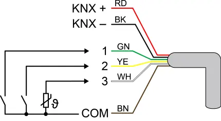
- Figure 2: Wiring diagram for control cable inputs (KNX and binary inputs).
- Figure 3: Mounting example in an electronic device box with a partition wall.
- Figure 4: Required 4mm spacing between mains and bus cables.
Model compatibility
- Requires KNX system.
- Compatible with ETS version 5.7.3 and above.
- Suitable for AC motors 110...230 V.

Manual page author
David Miller
Documentation analyst
Organizes user manual content into clear summaries, with attention to model details, product context, and everyday usability.