Lighting / Controllers & Dimmers
User Manual for Niko 410-00351 Wireless 2-Channel Receiver
Comprehensive user guide for the Niko 410-00351 Wireless 2-Channel Receiver. Includes installation instructions, operating modes, programming steps for transmitters and timers, and technical specifications.
Quick answers from the manual
Quick answer
- The Niko 410-00351 is a 2-channel wireless receiver for DIN rail mounting. It supports various operating modes including ON/OFF, PULSE, TIMER, PUSH BUTTON, and LOGIC, and is compatible with Easywave transmitters. p. 1
Key actions
- Programming a transmitter p. 2
- Programming a timer p. 2, 3
- Resetting to factory settings p. 4
Problems and fixes
Transmitter not working
Ensure the transmitter is correctly programmed to the receiver output.
p. 2Maintenance and reset
- Resetting an output p. 4
- Factory reset p. 4
Technical specifications
| Parameter | Value | Meaning | Pages |
|---|---|---|---|
| Frequency | 868.30 MHz | Operating frequency | p. 4 |
| Output | 2 x 16A | Max load per contact | p. 4 |
Where to find it in the PDF
- Installation and Description p. 1
- Operating Modes p. 2
- Programming p. 2, 3
- Specifications p. 4
Table of contents
Manual images
Click an image to enlargeQuick guide from the manual
The Niko 410-00351 is a 2-channel wireless receiver designed for DIN rail mounting. It is used to activate electrical devices using Easywave protocol transmitters. Key operations include programming transmitter codes, setting timer durations, and resetting the device to factory settings.
Description
The 410-00351 features two potential-free contacts. It supports multiple operating modes: ON/OFF, PULSE, TIMER (fixed or programmable), PUSH BUTTON, and LOGIC. The device is intended for installation in dry rooms within a distribution box or control cabinet.
Installation
Warning: Installation must be performed by a qualified installer in accordance with applicable regulations.
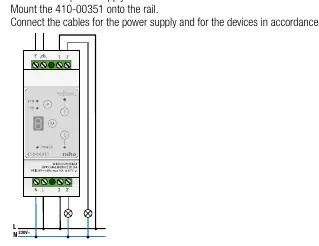
- Switch off the power supply.
- Mount the 410-00351 onto a standard DIN rail (35 x 7.5 mm).
- Connect power supply cables and device cables according to the connection diagram.
- Switch on the supply voltage.
Operating modes
The receiver supports several modes:
- ON/OFF: Standard switching.
- PULSE: Output activated for a set duration (1s).
- TIMER: Output switches ON for a programmed duration. Includes fixed (3 min, 7 min) and programmable (Individual/Global) options.
- PUSH BUTTON: Output active while the transmitter button is held down (max 36s).
- LOGIC: Combines transmission codes using AND/OR logic (only in 2-button operation).
Programming
Programming is performed using the buttons on the receiver and the transmitter. 32 transmission codes can be programmed per output.
Programming a transmitter
- Start programming mode (1x or 2x press on the receiver).
- Select operating mode (OM) using the Mode button.
- Select the switching output.
- Send the transmission code from the transmitter.
Programming the Timer
Switching times for modes 4 and 5 are calculated using a base time and a multiplier. The maximum base time is 60 seconds.
- Start programming mode and select timer mode (4 or 5).
- Select the output.
- Select the base time (> 1.6s).
- Save the base time.
- Select the multiplier (A, C, E, F, H).
- Save the switching time.
Resetting
- Resetting an output: Deletes all programmed transmitters and resets switching times for a specific output.
- Factory reset: Press and hold the Mode button and Channel 1 + Channel 2 buttons simultaneously using 3 fingers.
Specifications
- Frequency: 868.30 MHz
- Protocol: Easywave
- Power supply: 230 V AC 50 Hz
- Output: 2 potential-free contacts, max 16 A / 230 V (normally open)
- Operating temperature: -20 °C to +45 °C
Practical help
Common problems
Transmitter not working
Ensure the transmitter is correctly programmed to the receiver output. If it was previously programmed, it may need to be re-programmed.
LOGIC mode not working
LOGIC mode only functions in 2-button operation and requires all other operating modes to be OFF.
Timer duration incorrect
Verify the multiplier setting (A, C, E, F, H) and ensure the base time was programmed correctly.
Before use
- Switch off power supply before installation
- Ensure DIN rail is 35 x 7.5 mm
- Verify load type against the load table
- Ensure transmitters follow the Easywave protocol
Specs in practice
- Operating Temperature
- -20°C to +45°C
Images and diagrams
- Wiring diagram shows connection to 230V power supply and load
- Display indicators show LED status for power, 2TB, 1TB, and outputs
Model compatibility
- Compatible with Easywave protocol transmitters
- Not compatible with LOGIC function in 1-button operation

Manual page author
David Miller
Documentation analyst
Organizes user manual content into clear summaries, with attention to model details, product context, and everyday usability.