Computers / Cooling Systems
AZZA Hurricane III Digital RGB Fan 120mm
Quick guide for the AZZA Hurricane III Digital RGB Fan 120mm. Learn how to connect to motherboard ARGB headers, daisy-chain fans, and install the AZZA Hub for lighting control.
Table of contents
Manual images
Click an image to enlargeQuick guide from the manual
The AZZA Hurricane III Digital RGB Fan is designed for 5V addressable RGB headers. Warning: Do not connect these fans to 12V non-addressable headers, as this will cause permanent damage to the LED strip. Ensure your motherboard supports 5V addressable RGB (e.g., ASUS, MSI, Gigabyte, ASRock) before installation.
Motherboard connection
To connect the fan directly to your motherboard:
- Locate the 5V addressable RGB header on your motherboard.
- Connect the fan's digital RGB connector to the header.
- Ensure the pinout matches the 5V, Data, and Ground configuration shown in the manual.
Daisy-chaining fans
You can connect multiple fans in a parallel configuration (daisy-chaining):
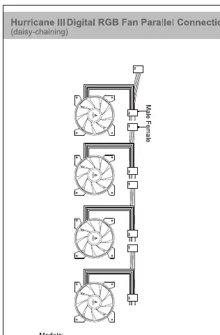
- Use the male and female connectors on the fan cables to link fans together.
- Important limit: Do not daisy-chain more than 5 fans per single motherboard header. Each fan contains digital/addressable LED diodes, and the WS2812B standard supports up to 60 diodes maximum per header.
AZZA Hub installation
If using the included AZZA Hub:
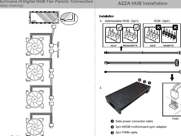
- Connect the SATA power connector cable to your power supply.
- Connect the 3-pin ARGB motherboard sync adapter to your motherboard's ARGB header.
- Connect the 4-pin PWM cable to the motherboard's fan header.
- Connect the fans to the ARGB ports on the hub.
AZZA Hub functions
The hub provides the following features:
- Ports: 3x ARGB ports, 6x 4-pin PWM fan ports, 1x 2-pin connector for Reset/LED switch, 1x SATA power connector, 1x 3-pin ARGB connector to motherboard, 1x 4-pin PWM connector to motherboard.
- Lighting control: Supports 17 lighting modes. Modes can be controlled by the Reset/LED switch on the case or by the motherboard software.
- Control switch: Hold the LED button for 3 seconds to switch the RGB control function between motherboard software and the LED button.
- Mounting: The hub includes a magnet on the back for easy installation inside metal cases.
Practical help
Common problems
Fan LEDs not lighting up or damaged
Ensure the fan is connected to a 5V addressable header. Connecting to a 12V non-addressable header will cause damage.
Lighting sync issues
Verify your motherboard supports 5V ARGB. Hold the LED button on the hub for 3 seconds to toggle between motherboard sync and manual control.
Too many fans connected
Do not daisy-chain more than 5 fans per single motherboard header to avoid exceeding the 60-diode limit.
Before use
- Verify your motherboard has a 5V addressable RGB header (not 12V).
- Check that your motherboard is compatible with 5V ARGB (e.g., ASUS, MSI, Gigabyte, ASRock).
- Ensure you have a SATA power connector available if using the AZZA Hub.
- Confirm you are not exceeding 5 fans per header when daisy-chaining.
Specs in practice
- 5V Addressable Header
- Required for digital RGB control; do not connect to 12V headers.
- Daisy-chaining
- Connecting multiple fans in a series; limited to 5 fans per header.
- WS2812B-compliant
- The standard for the digital LEDs used in these fans.
Images and diagrams
- Motherboard Connection: Shows the pinout for 5V Digital RGB headers.
- Daisy-chaining: Shows how to connect fans in parallel using the male/female connectors.
- AZZA Hub: Shows the connection of SATA power, PWM, and ARGB sync cables.
Model compatibility
- Compatible with 5V addressable headers from MSI, ASUS, Gigabyte, and ASRock.
- Not compatible with 12V non-addressable headers.

Manual page author
Emily Carter
User documentation editor
Prepares concise manual descriptions and highlights the most useful setup, operation, and maintenance information for readers.