Computers / Cooling Systems
User Manual for Silverstone VISTA 120 ARGB Cooling Fan
Quick guide for the Silverstone VISTA 120 ARGB cooling fan. Includes installation steps, wiring diagrams, and connector definitions for PWM and ARGB lighting control.
Table of contents
Manual images
Click an image to enlargeImportant Information
The Silverstone VISTA 120 ARGB is a performance-enhanced 120mm PWM fan featuring an integrated ARGB controller. The controller allows for manual lighting mode switching via a button or synchronization with the motherboard. Ensure your motherboard supports 5V ARGB headers for full synchronization capabilities.
Connector Definitions
The system utilizes several connectors for fan operation and lighting control:
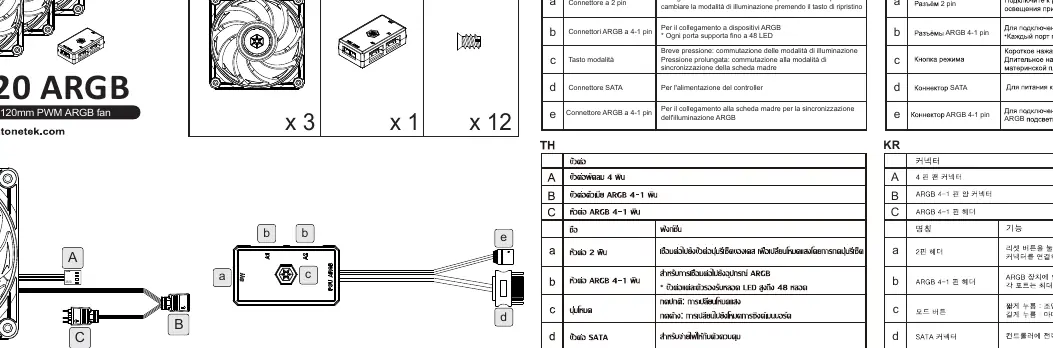
- A: 4-pin fan connector (connects to motherboard fan header).
- B: ARGB 4-1 pin header (for connecting ARGB devices; each port supports up to 48 LEDs).
- C: ARGB 4-1 pin female connector.
- a: 2-pin header (connects to case reset button to change lighting modes).
- b: ARGB 4-1 pin headers.
- c: Mode button (Short press: switch lighting modes; Long press: switch to motherboard sync mode).
- d: SATA connector (power for the controller).
- e: 4-1 Pin ARGB connector (connects to motherboard for sync).
Installation Guide
Follow these steps to install and connect your cooling fan:
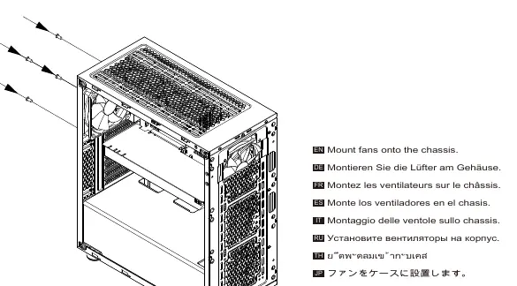
Step 1: Mounting
Secure the fans onto the chassis using the provided mounting hardware.
Step 2: PWM Connection
Connect the 4-pin PWM connector from the fan to the motherboard's fan header (labeled M/B FAN / PWM Header).
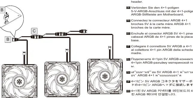
Step 3: ARGB Connection
Connect the 4+1-pin 5V ARGB connector to the motherboard's 4+1-pin ARGB header to enable lighting synchronization.
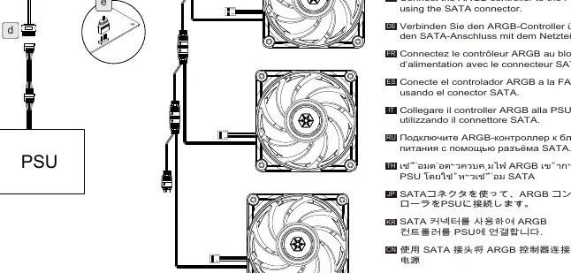
Step 4: Power Connection
Connect the ARGB controller to your power supply unit (PSU) using the SATA connector.
Manufacturer information
SilverStone Technology Co., Ltd.
Practical help
Common problems
Lighting not syncing with motherboard
Ensure you have performed a long press on the Mode button to switch the controller into motherboard sync mode.
Fan not spinning
Verify that the 4-pin PWM connector is securely connected to the motherboard fan header.
Lighting mode not changing via case button
Check that the 2-pin header is correctly connected to the case's reset button connector.
Before use
- Ensure your motherboard has an available 4-pin PWM fan header.
- Verify your motherboard supports 5V ARGB headers for synchronization.
- Check that your power supply has an available SATA connector.
- Confirm the case has a reset button if you intend to use manual lighting control.
Specs in practice
- PWM Connector
- 4-pin header used for motherboard-controlled fan speed regulation.
- ARGB Connector
- 4-1 pin header for addressable RGB lighting control.
- SATA Connector
- Power input required to operate the ARGB controller.
Images and diagrams
- The manual provides a wiring diagram illustrating the connection path from the fan to the motherboard (PWM/ARGB) and the PSU (SATA power).
Model compatibility
- Each ARGB port on the controller supports up to 48 LEDs.

Manual page author
David Miller
Documentation analyst
Organizes user manual content into clear summaries, with attention to model details, product context, and everyday usability.