HVAC / Air Conditioners
Installation Instructions for Bard QWSCRV Commercial Room Ventilator
A comprehensive installation and configuration guide for the Bard QWSCRV Commercial Room Ventilator. Includes blade adjustment procedures, potentiometer settings, CO2 sensor setup, and wiring diagrams for QW*S series heat pumps.
Quick answers from the manual
Quick answer
- The QWSCRV is an electromechanical ventilation system for Bard QW*S series heat pumps. It uses potentiometers on the control board to adjust damper blade positions for different operation modes (Blower Only, Part Load, Full Load). p. 3
Key actions
- Adjusting Blade Position p. 4
- Setting Pre-Purge Time p. 7
Technical specifications
| Parameter | Value | Meaning | Pages |
|---|---|---|---|
| CO2 Control Band | 700-1500 ppm | Recommended setting for CO2 control; local standards may vary. | p. 8 |
Where to find it in the PDF
- Installation and Adjustment p. 3
- Control Board Settings p. 7
- CO2 Sensor Setup p. 9
- Wiring Diagram p. 10
Table of contents
Manual images
Click an image to enlargeQuick Guide
The QWSCRV is an electromechanical ventilation system designed for Bard QW*S series geothermal heat pumps. It automatically adjusts fresh air intake based on the unit's operation mode. Key tasks include adjusting damper blade positions using potentiometers on the control board and configuring CO2 sensors if used.
Description
The QWSCRV ventilator provides fresh air to meet indoor air quality standards. It is a spring-return system that closes upon loss of power. It adjusts to different modes of operation, such as blower only, part load cooling, and full load cooling, to maintain consistent fresh air intake levels.
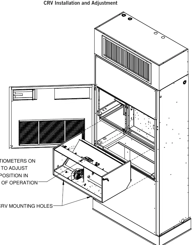
Blade Adjustment
The amount of ventilation air depends on return air pressure, supply air static pressure, indoor blower motor speed, building envelope tightness, and the damper blade open position. To adjust the blade position:
- Blower Only: Energize the evaporator blower (manual fan position). Locate potentiometer OCC on the control board and adjust until the damper position aligns with the numerical location on the label per the graph.
- Part Load (Stage 1): Energize the evaporator blower and compressor (heat or cool mode). Locate potentiometer Y1 on the control board and adjust until the damper position aligns with the numerical location on the label per the graph.
- Full Load (Stage 2): Energize the evaporator blower and compressor (heat or cool mode). Locate potentiometer Y2 on the control board and adjust until the damper position aligns with the numerical location on the label per the graph.
"V" Option Sequence of Operation
The "V" option includes a control board with adjustable potentiometers:
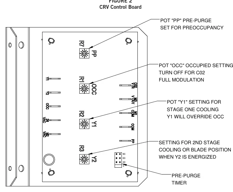
- PP (Pre-Purge): Adjusts blade setting for outdoor air intake during a pre-purge cycle. The cycle time (0, 30, 60, or 90 minutes) is set using the PP jumper.
- OCC (Occupied): Adjusts blade setting when the "A" terminal is energized.
- Y1: Adjusts blade setting when the "Y1" terminal is energized (1st stage cooling/Balanced Climate). Overrides OCC.
- Y2: Adjusts blade setting when the "Y2" terminal is energized (2nd stage cooling). Overrides OCC and Y1.
2-10V Operation
A CO2 sensor or other device sending a 2-10V signal can control the damper motor. Two methods are available:
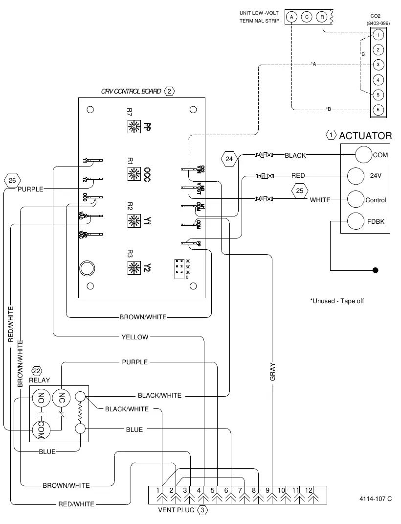
- Method 1: Control board accepts a 2-10VDC signal (resistive load > 5000 ohms). Connect the CO2 sensor output to the gray wire in position 9 on the 12-pin vent plug.
- Method 2: Bypass the control board and power the motor directly from the device (resistive load < 5000 ohms). Splice the gray wire (2-10V IN) with the white wire (2-10V OUT) and connect the signal to the gray wire in position 9.
CO2 Sensor Setup
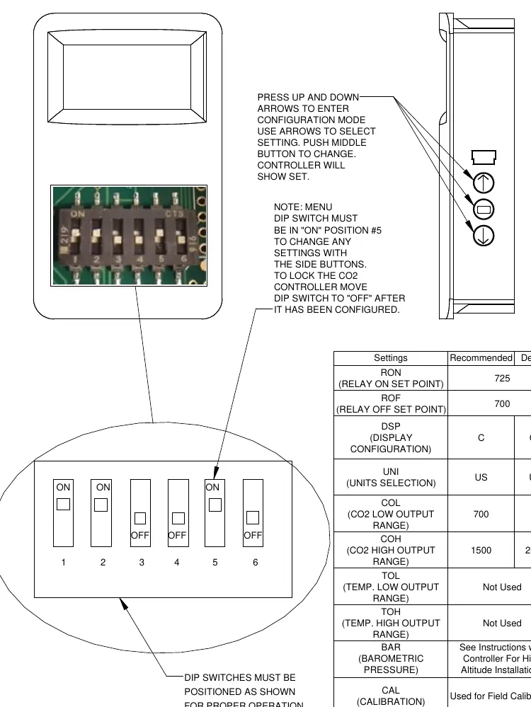
For the 8403-096 CO2 sensor, ensure the menu DIP switch is in the "ON" position (#5) to change settings. Use the up/down arrows to enter configuration mode and the middle button to change settings. Recommended control band is 700-1500 ppm.
Practical help
Common problems
Ventilator remains closed
This is normal behavior; the ventilator is spring-return and will return to the closed position upon loss of power.
Incorrect ventilation air volume
Verify return air pressure, supply air static pressure, indoor blower motor speed, and ensure damper blade settings are adjusted correctly for the specific mode of operation.
Before use
- Verify compatibility with Bard QW*S series geothermal heat pumps.
- Ensure power is disconnected before performing wiring or adjustments.
- Have a small screwdriver ready for potentiometer adjustments.
- Identify the correct graph for your specific model (QW2S, QW3S, QW4S, or QW5S).
Specs in practice
- PP Potentiometer
- Adjusts blade setting for pre-purge cycle; timer set via PP jumper.
- OCC Potentiometer
- Adjusts blade setting for occupied mode (A terminal energized).
- Y1 Potentiometer
- Adjusts blade setting for 1st stage cooling/Balanced Climate; overrides OCC.
- Y2 Potentiometer
- Adjusts blade setting for 2nd stage cooling; overrides OCC and Y1.
Images and diagrams
- CRV Control Board: Shows location of potentiometers (PP, OCC, Y1, Y2) and timer settings.
- CO2 Sensor Setup: Shows DIP switch configuration for 8403-096 sensor.
Model compatibility
- Designed for use with Bard QW*S Series Geothermal 2-Stage Heat Pumps.

Manual page author
Michael Turner
Technical manual editor
Reviews PDF manuals for structure, safety notes, and practical product details so readers can find the right information quickly.