Industrial / Access Control
User Manual for BEA 10STRIKECUV Universal Cylindrical Electric Strike
Quick guide for the BEA 10STRIKECUV Universal Cylindrical Electric Strike. Includes installation steps, wiring diagrams, technical specifications, and fail-safe/fail-secure configuration instructions.
Table of contents
Manual images
Click an image to enlargeQuick guide from the manual
The BEA 10STRIKECUV is a universal cylindrical electric strike designed for access control doors. This guide covers the essential installation, wiring, and configuration steps. Always ensure compliance with local safety standards (e.g., ANSI A156.31) and NFPA70 wiring methods. Before beginning, ensure all power to the electrical enclosure is shut off.
Technical Specifications
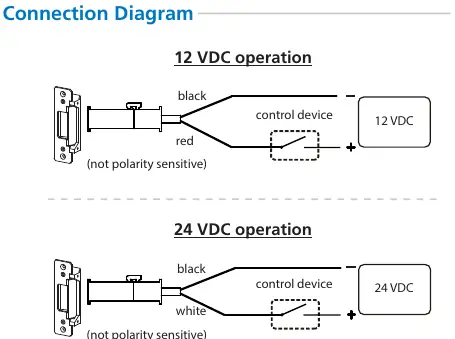
- Operating voltage: 12 or 24 VDC
- Current draw: 300mA (12 VDC) / 150mA (24 VDC)
- Operating temperature: 32 – 120 °F (0 – 49 °C)
- Humidity: 0 – 85% non-condensing
- Latch throw: 9/16" (15mm) max
- Static strength: 1000 lbs (454kg)
- Endurance: 250,000 cycles (UL-tested)
Installation and Wiring
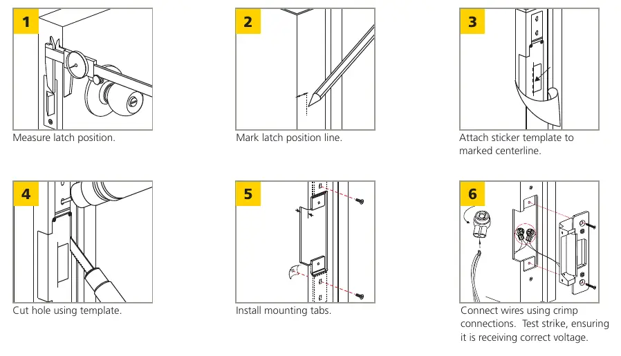
- Measure: Determine the latch position on the door frame.
- Mark: Mark the latch position line.
- Template: Attach the sticker template to the marked centerline.
- Cut: Cut the hole using the template.
- Install: Install the mounting tabs.
- Connect: Connect wires using crimp connections. Test the strike to ensure it is receiving the correct voltage.
Note: A proper gap must be reserved between the strike keeper and the latch bolt to prevent failure of the solenoid valve.
Fail-safe / Fail-secure Configuration
The unit is reversible. To change the setting:
- Remove the locking screw.
- Loosen, slide, and tighten the sliding screw to the desired setting.
- Reinsert and tighten the locking screw.
- Fail-safe: Move the sliding screw to the right.
- Fail-secure: Move the sliding screw to the left.
Safety and Compliance
- Indoor use only.
- Intended for use with UL-listed exit hardware.
- Must not impair the operation of emergency exits or cylindrical levers.
- Always dissipate ESD charge before handling circuit boards.
- Do not attempt internal repairs; contact BEA, Inc. for service.
Manufacturer information
BEA Sensors
Practical help
Common problems
Solenoid valve failure
Ensure a proper gap is reserved between the strike keeper and the latch bolt.
Unexpected door reactions during testing
Always stop pedestrian traffic through the doorway when performing tests.
Circuit board damage
Dissipate body ESD charge before handling any board.
Before use
- Verify power supply is 12 or 24 VDC.
- Ensure latch throw is 9/16" (15mm) max.
- Check that door hardware is UL-listed.
- Shut off all power before wiring.
- Ensure all industry signage and warning labels are in place.
Specs in practice
- Operating voltage
- Supports 12V or 24V DC power sources.
- Current draw
- 300mA at 12V or 150mA at 24V.
- Static strength
- Rated for 1000 lbs (454kg) of force.
Images and diagrams
- Connection Diagram: Illustrates wiring for 12V and 24V operations; note that connections are not polarity sensitive.
- Fail-safe/Fail-secure: Shows the sliding screw mechanism used to toggle between power-to-open and power-to-lock modes.
Model compatibility
- Designed for cylindrical or mortise locksets.
- Must be used with UL-listed exit hardware.
- Wiring must be in accordance with NFPA70.

Manual page author
Emily Carter
User documentation editor
Prepares concise manual descriptions and highlights the most useful setup, operation, and maintenance information for readers.