Industrial / Access Control
User Guide for BEA 10MAGLOCK3UL Electromagnetic Lock
Quick guide for the BEA 10MAGLOCK3UL electromagnetic lock. Includes installation instructions, wiring diagrams, technical specifications, and safety precautions for proper setup.
Table of contents
Manual images
Click an image to enlargeQuick guide from the manual
This guide provides essential information for the installation and operation of the BEA electromagnetic lock series. Ensure the product is powered by a UL-listed, regulated, and power-limited power supply. The lock is designed for indoor, dry applications on doors between 1 3/8 and 2 inches thick. Always shut off power before performing any wiring procedures.
Specifications
The electromagnetic locks are available in single and double configurations with optional door status sensors. Key specifications include:
- Input Voltage: 12 or 24 VDC
- Operating Temperature: 32 – 120 °F (0 – 49 °C)
- Operating Humidity: 0 – 85%
- Bond Status Relay: 1.0 A @ 24 VDC resistive
- Door Status Switch: Dry contacts, 3W (0.25 amps max, 30VDC max)
- Certification: UL294
Precautions
Safety is critical during installation. Always maintain a clean environment, be aware of pedestrian traffic, and ensure that moving door parts do not catch any wires. Compliance with local, national, and international regulations (such as ANSI/NFPA 70, NFPA 101, CSA C22.1) is required.
Mechanical Installation
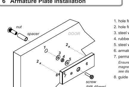
The armature plate must be installed correctly to ensure proper locking efficiency. Use the provided mounting template with the door in its normally closed position. Apply threadlocker to all screws before installing and firmly tighten them. Do not over-tighten the armature plate. The rubber washer is designed to allow the armature plate to automatically adjust its position for the best mating contact with the magnet.
Electrical Installation
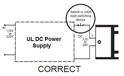
Wiring must be performed using 16-22AWG copper wire. Ensure the power selector jumper is set correctly for 12 VDC or 24 VDC operation. If the power switch is not wired between the DC source voltage and the magnet, the magnet may simulate residual magnetism, taking longer to de-energize.
Switches and Relay Contacts
The lock includes a lock status relay contact (SPDT) and an optional door status switch. Relay dry contacts are rated at 1A @ 24 VDC. For NO (Normally Open) configurations, connect wires to Terminal 3 and Terminal 4. For NC (Normally Closed) configurations, connect wires to Terminal 4 and Terminal 5.
Manufacturer information
BEA Sensors
Practical help
Common problems
Residual magnetism (slow release)
Ensure the power switch is wired between the DC source voltage (+) and the magnet.
Reduced locking efficiency
Check for damage to the mating surfaces of the magnet and armature plate. Ensure the armature plate is not over-tightened.
Armature plate misalignment
Ensure the rubber washer is installed correctly to allow the plate to pivot and self-adjust.
Before use
- Verify the power supply is UL-listed, regulated, and power-limited.
- Ensure door thickness is between 1 3/8 and 2 inches.
- Shut off all power before starting wiring.
- Apply threadlocker to all screws.
- Verify the power selector jumper matches the input voltage (12V or 24V).
- Check that moving door parts will not catch any wires.
Specs in practice
- Input Voltage
- Supports 12 or 24 VDC power sources.
- Bond Status Relay
- Rated for 1.0 A @ 24 VDC resistive load.
- Operating Temperature
- Must be installed in environments between 32 – 120 °F (0 – 49 °C).
Images and diagrams
- Armature plate assembly: Shows the correct sequence of the nut, spacer, washers, and guide pin.
- Wiring diagram: Illustrates the connection between the power supply, switching device, and the lock terminals.
Model compatibility
- Designed for indoor, dry applications only.
- Compatible with standard door types (1 3/8 to 2 inch thickness).
- Must be installed within the same room as other connected equipment.

Manual page author
Michael Turner
Technical manual editor
Reviews PDF manuals for structure, safety notes, and practical product details so readers can find the right information quickly.