Lighting / Fixtures
Installation Instructions for BELL Lighting Powertron Flood Light 11330/1/2
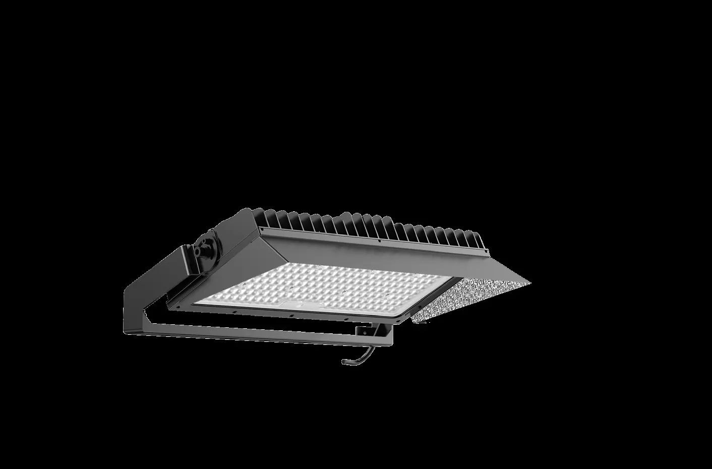
Comprehensive installation guide for the BELL Lighting Powertron Flood Light (11330/1/2). Includes wiring diagrams, mounting instructions, torque settings, and technical specifications for 600W, 1200W, and 1800W models.
Quick answers from the manual
Quick answer
- The Powertron Flood Light must be installed by a qualified electrician in accordance with BS7671:2018 regulations. It is available in 600W, 1200W, and 1800W variants, each requiring specific mounting torque and wiring configurations. p. 1
Key actions
- Mounting the light p. 3
- Wiring the unit p. 7, 8
Technical specifications
| Parameter | Value | Meaning | Pages |
|---|---|---|---|
| IP Rating | IP66 | Ingress protection rating | p. 1 |
Where to find it in the PDF
- Installation Instructions p. 1, 2, 3, 4
Table of contents
Manual images
Click an image to enlargeImportant Information
This equipment must be installed by a competent electrician in accordance with current IEE wiring regulations (BS7671:2018) and local building control. BELL Lighting does not accept responsibility for claims arising from poor installation. The product is rated IP66.
Installation and Mounting
The Powertron Flood Light is available in 600W, 1200W, and 1800W variants. Ensure the mounting surface can support the weight of the unit (up to 170kg for the 1800W model).
Rotatable Angle and Torque
When mounting, adhere to the specified torque settings to ensure structural integrity:
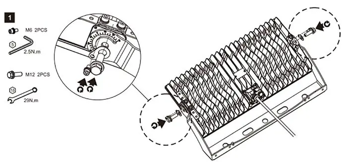
- 600W: 8 N.m and 29 N.m settings.
- 1200W: 8 N.m and 114 N.m settings.
- 1800W: 114 N.m setting.
Refer to the diagrams in the manual for allowed and disallowed mounting positions to ensure proper heat dissipation and structural safety.
Mounting Accessories
The manual provides instructions for installing optional accessories:
- Laser Device Mount: Requires separate purchase of bracket and lens.
- Safety Rope Mount: Essential for securing the unit.
- Visor Mount: Secured with M4 screws at 1.2 N.m torque.
Wiring
Wiring diagrams are provided for different models:
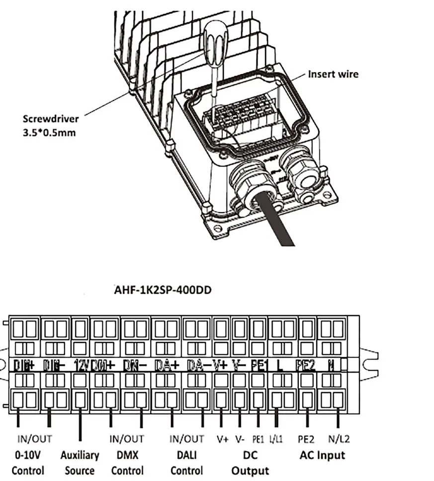
- 600W Wiring: Connect input cable to the junction box, ensuring correct L, N, and GND connections.
- 1200W/1800W Wiring: Follow the remote driver wiring diagram, ensuring correct connections for AC input, DMX, and LED outputs.
Technical Specifications
The manual includes detailed physical dimensions and EPA (Effective Projected Area) data for all models. When installing in confined spaces, ensure minimum clearance distances are maintained to prevent overheating. The maximum number of luminaires per circuit breaker depends on the MCB type (B or C) and input voltage; consult the provided tables in the manual for specific configurations.
Manufacturer information
BELL Lighting
Practical help
Common problems
Incorrect installation
Must be installed by a qualified electrician complying with BS7671:2018.
Overheating in confined spaces
Ensure minimum clearance distance as specified in the manual (e.g., 200mm/100mm/70mm).
Loose connections
Follow specified torque settings (e.g., 8Nm, 29Nm, 114Nm) for mounting bolts.
Before use
- Verify the model (600W, 1200W, or 1800W).
- Ensure a qualified electrician is available for installation.
- Check local building control regulations.
- Confirm mounting surface can support the weight (up to 170kg for 1800W).
- Check for required MCB type (B or C) based on voltage.
Images and diagrams
- Wiring diagrams show input/output connections for different wattages.
- Rotatable angle diagrams indicate allowed and disallowed mounting positions.
- Clearance distance diagrams show required spacing for heat dissipation.
Model compatibility
- Requires specific MCB types (B or C) depending on wattage and voltage.
- Designed for professional installation only.

Manual page author
Emily Carter
User documentation editor
Prepares concise manual descriptions and highlights the most useful setup, operation, and maintenance information for readers.