Tools / Welding Equipment
User Manual for Bormann BIW Series Electric Welding Inverter
Quick guide for Bormann BIW series electric welding inverters (BIW1540, BIW1560, BIW1580, BIW1700, BIW2100, BIW1410, BIW1610, BIW1810). Includes setup, safety, operation, and troubleshooting.
Table of contents
Quick guide from the manual
This manual provides essential safety, installation, and operating instructions for the Bormann BIW series welding inverters. Before using the equipment, ensure the input voltage is within the 200V-240V range. Always wear appropriate safety gear, including protective clothing, gloves, and eye protection, to guard against arc light and welding sparks. Ensure the machine is placed on a stable, horizontal surface with a slope not exceeding 15° and maintain at least 0.3m of clearance for ventilation.
Description of main parts
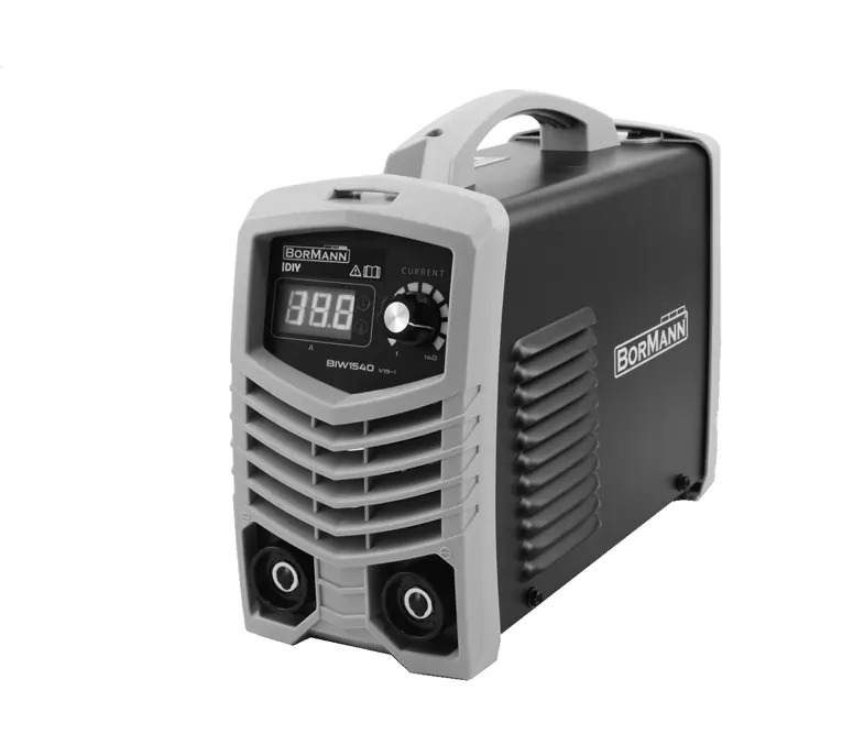
- 1. Electrode holder clamp socket (+)
- 2. Display screen
- 3. Welding current adjusting knob
- 4. Ventilation ports
- 5. Earth clamp connecting socket (-)
- 6. Fan
- 7. ON/OFF switch
- 8. Power cable
- 9. Arc Force adjusting knob
Installation and operating instructions
Connect the electrode holder and earth clamp by inserting the quick connector into the respective socket and twisting it clockwise. Ensure a correct fit and pay attention to connection polarity. Generally, reverse polarity is used (electrode holder to negative, earth clamp to positive), but the machine supports both straight and reverse polarity based on manufacturer recommendations. If you experience an unstable arc or electrode sticking, check the polarity. Turn the machine on using the rear switch and set the amperage knob according to the welding rod type and size.
Maintenance
Regularly remove dust from the machine using dry, clean compressed air. If operating in a dusty or smoky environment, clean the machine monthly. Ensure output terminals are tightly connected and connectors are undamaged. If the machine will not be used for a long period, store it in a cool, dry place.
Troubleshooting
If the power indicator is not lit and the fan is not working, check the power switch, connections, and supply voltage. If the QC LED is permanently on, the machine may be in overheat protection (wait 15 minutes) or over-current protection (turn off for 30 seconds). If the output current is unstable, check for supply voltage fluctuations or poor cable connections.
Technical Data
The BIW series includes models BIW1540, BIW1560, BIW1580, BIW1700, BIW2100, BIW1410, BIW1610, and BIW1810. Most models operate on 220V-230V input, with output currents ranging from 10A to 200A depending on the model. All models feature a 60% rated duty cycle.
Practical help
Common problems
Power indicator not lit, fan not working, no output
Check power switch, connections from switch to power board, plug point, and supply voltage.
Power indicator lit, fan working, no output
Check if all cables are connected properly and if the output connector is damaged.
QC LED is on
Machine may be in overheat protection (wait 15 minutes) or over-current protection (turn off for 30 seconds).
Output current is not stabilized
Check for unstable supply voltage, interference, or bad connections on earth cable/electrode holder.
Before use
- Verify input voltage is 200V-240V.
- Ensure the machine is placed horizontally (slope < 15°).
- Check that ventilation ports are not covered (0.3m clearance).
- Ensure proper grounding.
- Check cable connections are tight and polarity is correct.
- Verify welding rod type and size.
Specs in practice
- Rated duty cycle
- The percentage of a 10-minute period the machine can operate at rated output current.
- No-load voltage
- The voltage present at the output terminals when the machine is on but not welding.
- Input voltage
- The required power supply range (220V-230V) for the machine to function correctly.
Images and diagrams
- Front panel: Contains the display, current adjustment knob, and sockets for electrode holder and earth clamp.
- Rear panel: Contains the ON/OFF power switch and power cable.
Model compatibility
- Designed for welding low-carbon steel; consult supplier for other materials.
- Not intended for commercial, trade, or industrial applications.

Manual page author
Michael Turner
Technical manual editor
Reviews PDF manuals for structure, safety notes, and practical product details so readers can find the right information quickly.