Tools / Drills
Spare Parts List for Bosch AdvancedDrill 18V-80
Access the official spare parts list and exploded view for the Bosch AdvancedDrill 18V-80. Includes detailed wiring diagrams, screw torque specifications, and component identification for maintenance and repair.
Table of contents
Manual images
Click an image to enlargeImportant information from the spare parts list
This document provides the official exploded view, wiring diagram, and spare parts list for the Bosch AdvancedDrill 18V-80 (Model 3 603 JE2 000). It is intended for service and repair purposes. Always ensure the battery is removed before performing any maintenance or disassembly to prevent accidental activation.
Exploded View and Components
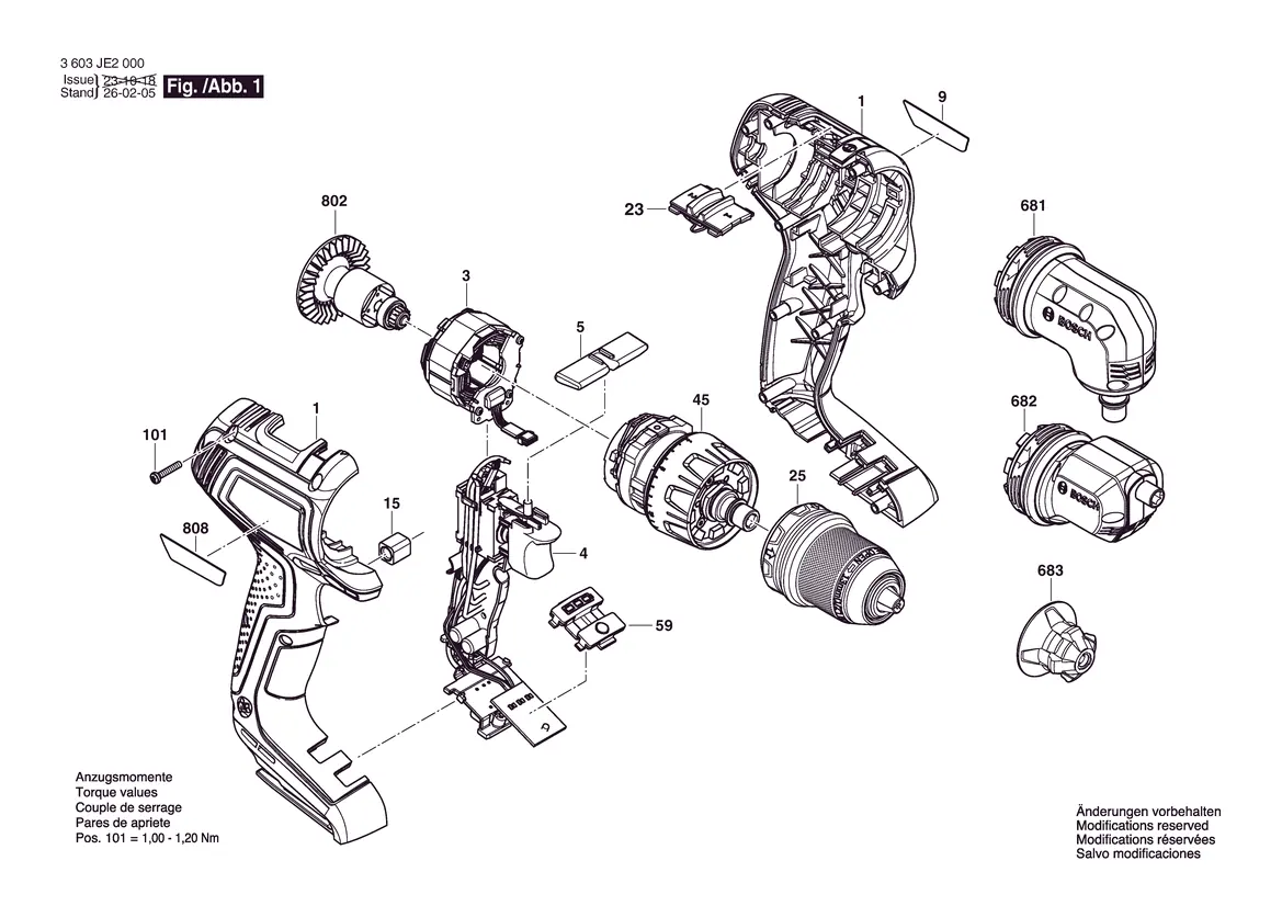
The exploded view illustrates the internal structure of the drill. Each component is numbered to correspond with the official Bosch spare parts catalog. Use this diagram to identify the correct placement of internal parts, including the motor, gearbox, and housing components.
Wiring and Electrical Connections
The wiring diagram details the routing of internal cables. Ensure all wires are connected to the correct solder pads as indicated:
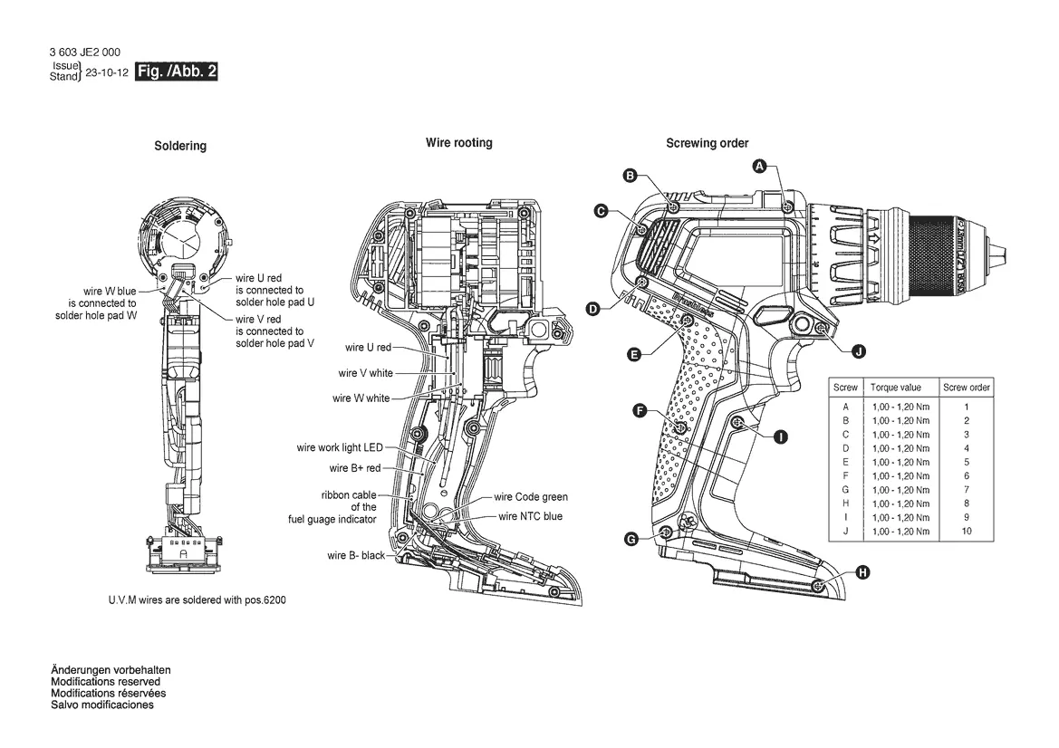
- Wire W (blue) to solder hole pad W
- Wire U (red) to solder hole pad U
- Wire V (red) to solder hole pad V
- U.V.M wires are soldered with pos. 6200
Assembly and Torque Specifications
When reassembling the tool, it is critical to follow the specified torque values to prevent damage to the housing or internal components.
- Housing Screws (Pos. 101): 1.00 - 1.20 Nm
- Screwing Order (A-J): Follow the sequence A through J as shown in the diagram, applying 1.00 - 1.20 Nm to each screw.
Accessories
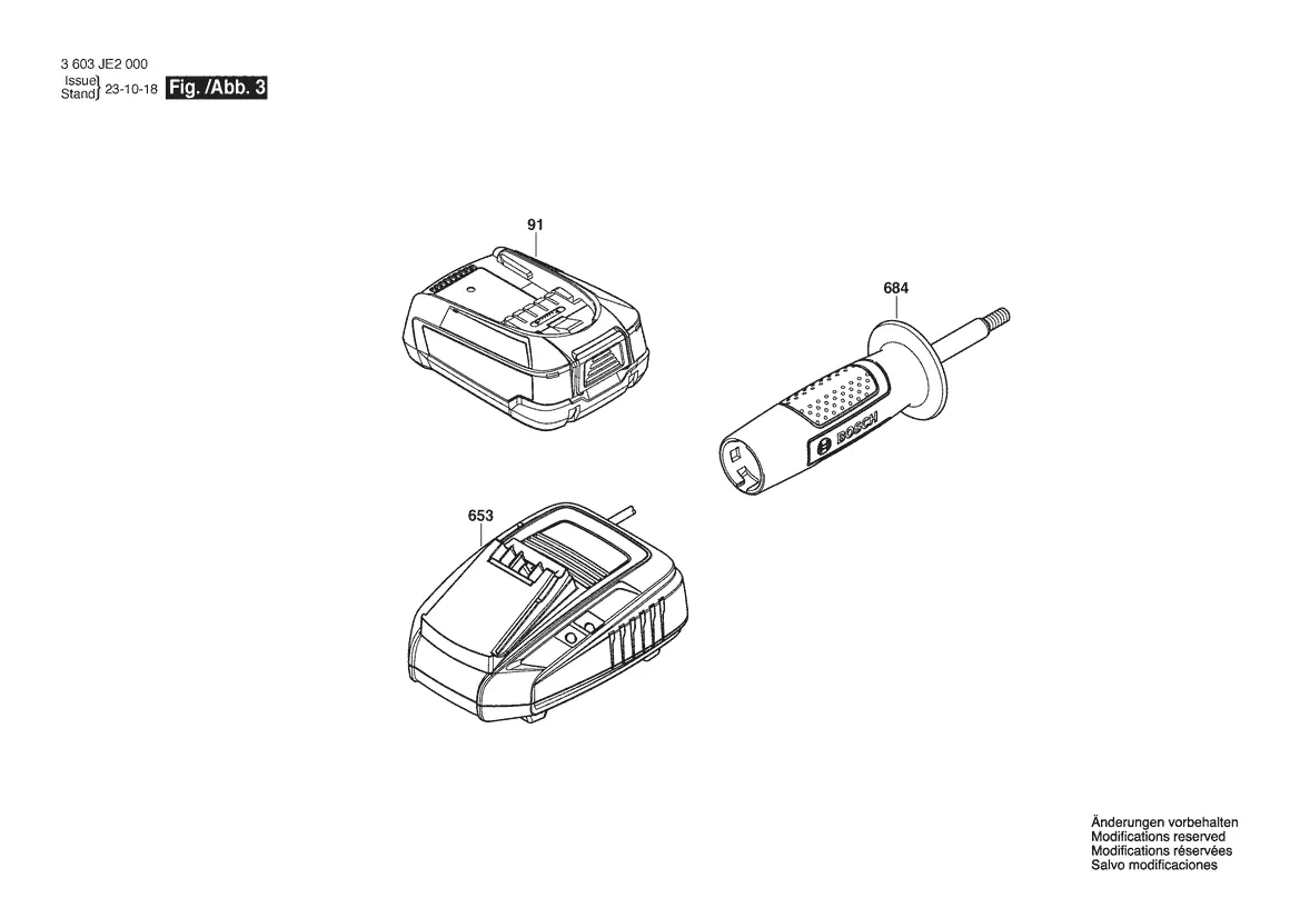
The document identifies compatible accessories, including the battery pack (91), charger (653), and auxiliary handle (684).
Manufacturer information
Bosch
Practical help
Common problems
Housing screws loose or stripped
Ensure screws are tightened to 1.00 - 1.20 Nm following the A-J sequence.
Wiring errors during reassembly
Refer to the wiring diagram on page 3 to verify color-coded connections to specific solder pads.
Before use
- Disconnect battery before opening the tool
- Verify the model number (3 603 JE2 000) matches your device
- Use a torque-controlled screwdriver set to 1.00 - 1.20 Nm
- Ensure all wires are routed correctly to avoid pinching
Specs in practice
- Torque Value
- 1.00 - 1.20 Nm is the required tightening force for housing screws to ensure structural integrity.
Images and diagrams
- Exploded view: Shows the assembly order of internal components.
- Wiring diagram: Details the specific solder pad connections for internal wiring.
- Screwing order: Defines the sequence (A-J) for tightening housing screws.
Model compatibility
- Compatible with Bosch 18V battery systems (Pos. 91).
- Compatible with standard Bosch chargers (Pos. 653).

Manual page author
Michael Turner
Technical manual editor
Reviews PDF manuals for structure, safety notes, and practical product details so readers can find the right information quickly.