HVAC / Thermostats & Controls
Braeburn 1020NC and 1220NC Non-Programmable Thermostat
Quick guide for the Braeburn 1020NC and 1220NC non-programmable thermostats. Includes installation steps, wiring configurations, system testing, user settings, and maintenance instructions.
Table of contents
Manual images
Click an image to enlargeQuick Guide
This guide covers the installation and operation of the Braeburn 1020NC and 1220NC thermostats. These models are designed for 24 Volt AC systems. Warning: Always turn off power to the heating or cooling equipment before beginning installation. Installation should be performed by experienced service technicians.
Installation
Install the thermostat approximately 5 feet (1.5m) above the floor in an area with good air circulation. Avoid locations affected by drafts, dead air spots, hot or cold air ducts, sunlight, appliances, or outside walls.
Steps to Install
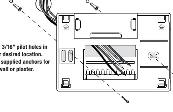
- Install the Sub-Base: Remove the sub-base from the thermostat body. Drill 3/16" pilot holes and mount the sub-base using supplied anchors.
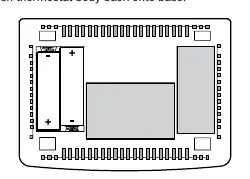
- Provide Power: Connect the common side of the transformer to the C terminal for 24V AC power. Alternatively, insert two AA alkaline batteries for primary or backup power.
- Connect Wires: Follow the wiring configuration specific to your system (Conventional or Heat Pump).
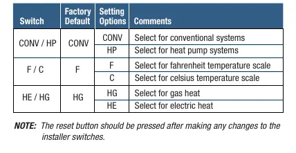
- Set Installer Switches: Configure the switches on the back of the thermostat for your specific system type (CONV/HP), temperature scale (F/C), and heat type (HE/HG).
- Attach Thermostat: Snap the thermostat body onto the sub-base and insert the quick reference card.
Wiring
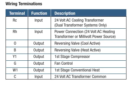
The thermostat supports various configurations. Ensure the correct wires are connected to the terminals: Rc, Rh, O, B, Y1, W1/E, G, W2, and C. For dual transformer systems, remove the factory-installed jumper. For heat pump systems, ensure the changeover valve (O or B) is selected correctly.
System Testing
Before testing, ensure the thermostat is properly installed. Do not short across terminals on the gas valve or control board. To test:
- Move the SYSTEM switch to HEAT and raise the set temperature by 3 degrees.
- Move the SYSTEM switch to COOL and lower the set temperature by 3 degrees (ensure outside temperature is above 50°F).
- Move the FAN switch to ON to verify fan operation.
Note: The thermostat includes an automatic compressor protection delay. If testing fails, press the reset button to return to factory defaults.
Operation
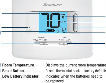
Use the SYSTEM switch to select COOL, OFF, or HEAT. The 1220NC model includes an EMER (Emergency Heat) position for heat pump systems. Use the FAN switch to select AUTO (fan runs only when system is running) or ON (fan runs continuously). Adjust the set temperature using the arrow buttons.
Maintenance
If batteries are installed, a low battery indicator will appear on the display when they need replacement. To replace, pull the thermostat body from the base, replace the two AA alkaline batteries, and snap the body back on. Clean the thermostat using a soft, damp cloth; never spray liquid directly on the unit or use abrasive cleansers.
Manufacturer information
Braeburn Systems LLC
Practical help
Common problems
System does not start
Check wiring connections, ensure power is supplied, or press the reset button to clear settings.
Compressor will not start
The thermostat has an automatic compressor protection delay; wait a few minutes or press the reset button to bypass.
Low battery indicator on display
Replace the two AA alkaline batteries immediately.
EMER option not available
If configured for a conventional system (CONV), the EMER option is not available.
Before use
- Turn off power to the heating or cooling equipment.
- Verify system compatibility (Conventional or Heat Pump).
- Ensure installation location is 5 feet above the floor.
- Have two AA alkaline batteries ready for backup or primary power.
- Ensure you have the correct wiring configuration for your system.
Specs in practice
- Electrical Rating
- 24 Volt AC (18-30V AC) with 1 amp maximum load per terminal.
- Control Range
- 45° – 90° F (7° – 32° C).
- Temperature Accuracy
- +/- 1° F (+/- .5° C).
Images and diagrams
- Wiring Terminals: Rc, Rh, O, B, Y1, W1/E, G, W2, C.
- Installer Switches: CONV/HP (System Type), F/C (Temperature Scale), HE/HG (Heat Type).
Model compatibility
- 1020NC: Single stage heat/cool conventional and heat pump.
- 1220NC: Up to 2 heat/1 cool conventional and heat pump.
- Compatible with 250-750 millivolt heat only systems.

Manual page author
Michael Turner
Technical manual editor
Reviews PDF manuals for structure, safety notes, and practical product details so readers can find the right information quickly.