Plumbing / Toilets Urinals
Installation Instructions for Caroma Cube 0.8L Cleanflush Electronic Series II Urinal Suite
Quick installation guide for the Caroma Cube 0.8L Cleanflush Electronic Series II Urinal Suite. Includes mounting instructions for inwall, induct, and inceiling setups, electrical connection details, and pressure adjustment settings.
Table of contents
Manual images
Click an image to enlargeQuick guide from the manual
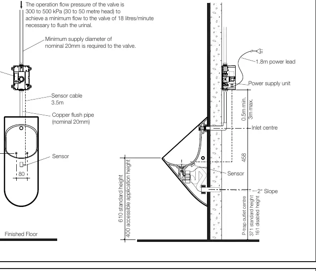
This document provides installation instructions for the Caroma Cube 0.8L Cleanflush Electronic Series II Urinal Suite. Before beginning, ensure all water lines are flushed to prevent debris from damaging the solenoid valve. The system requires a water pressure between 300 and 500 kPa and a minimum flow rate of 18 litres per minute.
Installation Requirements
- Water Pressure: 300 to 500 kPa (30 to 50 metres head).
- Flow Rate: Minimum 18 litres/minute.
- Supply Diameter: Nominal 20mm minimum.
- Electrical: 1.8m power lead provided; flexible electrical conduit (20mm or 25mm) is required for the sensor cable.
Installation Procedures
The urinal can be installed in three configurations: Inwall, Induct, or Inceiling. Ensure the flush valve is installed vertically and the flushpipe is straight to prevent water back-up.
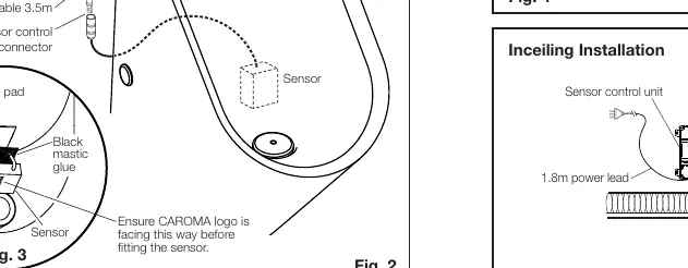
Sensor Installation
The sensor must be installed correctly to function:
- Clean the rectangle pad area at the back of the urinal to remove dust and grease.
- Apply the supplied mastic glue to the black plastic side of the sensor (opposite the label).
- Adhere the sensor to the urinal with the cable pointing upwards.
- Ensure the sensor is firmly attached.
Electrical Connections
Connect the Solenoid Valve to the sensor control unit, and the Power Supply Unit to the sensor control unit. Do not switch on the power supply until all electrical work is completed. Surge protectors are recommended to protect the transformer and electronic control module.
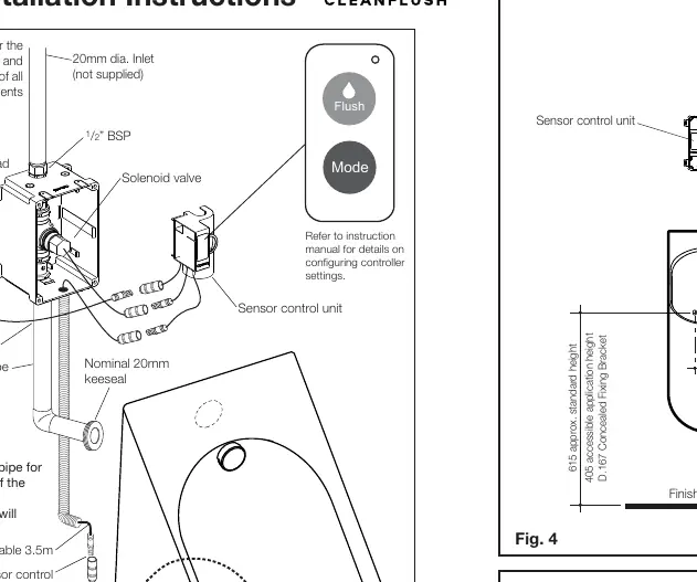
Configuration and Pressure Adjustment
The unit is factory preset to discharge 0.8 litres at 300-400 kPa inlet pressure. If the inlet pressure is between 401-500 kPa, you must adjust the setting:
- Press and hold the controller FLUSH button for 5 seconds to change the pressure setting.
To verify the discharge volume, activate the flush valve by waving your hand in front of the sensor and measure the water output using a container.
Cleaning and Maintenance
The product is subject to normal wear and should be checked regularly. Clean the glazed surface using a mild household detergent or warm soapy water. All service must be performed by an authorised service person.
Practical help
Common problems
Water back-up occurs
Ensure the flushpipe is installed vertically and straight.
Power spikes affecting electronics
Use surge protectors for the transformer and electronic control module.
Incorrect flush volume
If inlet pressure is 401-500 kPa, press and hold the controller FLUSH button for 5 seconds to adjust the setting.
Before use
- Flush water lines before installing the solenoid valve.
- Verify water pressure is between 300-500 kPa.
- Ensure minimum supply diameter of 20mm.
- Install flexible electrical conduit for the sensor cable.
- Ensure the sensor cable is pointing upwards during installation.
- Check for leaks after installation.
Specs in practice
- Operation flow pressure
- 300 to 500 kPa (30 to 50 metres head) required for proper operation.
- Minimum flow
- 18 litres/minute is necessary to flush the urinal.
- Sensor cable
- 3.5m length provided.
Images and diagrams
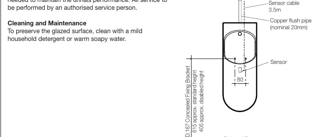
- Fig 1: Inwall installation details including bracket and outlet heights.
- Fig 2: Connection diagram for solenoid valve, sensor, and power supply.
- Fig 3: Correct orientation for sensor pad application.
- Fig 4: Induct installation setup.
- Fig 5: Inceiling installation setup.
Model compatibility
- Installation must be in accordance with AS/NZS 3500.2.
- Flexible electrical conduit (20mm or 25mm) is not supplied.

Manual page author
Emily Carter
User documentation editor
Prepares concise manual descriptions and highlights the most useful setup, operation, and maintenance information for readers.