Electronics / Projectors
Installation Guide for Chief 051RFCUB Fit Mobile Cart
A comprehensive installation and setup guide for the Chief 051RFCUB Fit Mobile Cart. This guide covers assembly, display mounting procedures for various VESA patterns, shelf installation, cable management, and essential safety and...
Table of contents
Manual images
Click an image to enlargeQuick Guide
The Chief 051RFCUB Fit Mobile Cart is designed for interactive displays between 55" and 86" with a maximum VESA pattern of 800x600. The maximum weight capacity for the display is 175 lbs (79.38 kg), and the accessory shelf supports up to 10 lbs (4.5 kg). Always ensure the cart is placed on a level surface and wheels are locked when stationary.
Assembly Instructions
Follow these steps to assemble the cart structure:
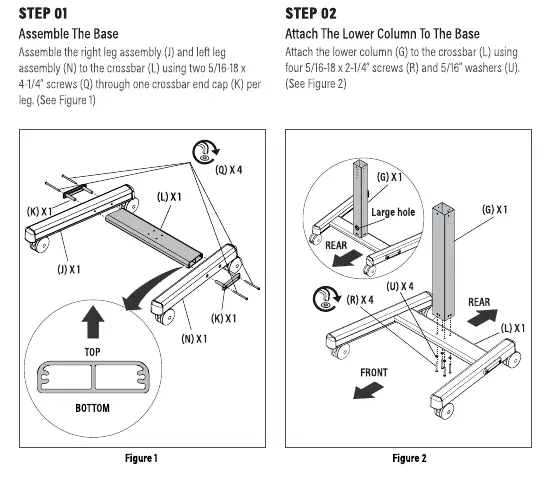


- Assemble the Base: Connect the right leg assembly (S) and left leg assembly (W) to the crossbar (U) using two 5/16-18 x 4-1/4" screws (AB) through the crossbar end caps (T). Ensure the rounded edges of the crossbar face up.
- Attach Lower Column: Secure the lower column (Q) to the crossbar (U) using four 5/16-18 x 2-1/4" screws (AC) and 5/16" washers (AF). Ensure the large hole in the column faces the back.
- Attach Face Plate: Install the face plate assembly (J) to the upper column (R) using one connector-stud (N), one connector-no stud (P), and four 5/16-18 flange nuts (AH). Choose one of three height positions.
- Connect Columns: Attach the upper column (R) to the lower column (Q) using four 10-24 x 1/2" flat head screws (AA). Ensure the large hole in the upper column faces the back.
Attaching the Display
There are two methods for mounting your display depending on the VESA pattern:
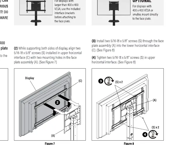
- For VESA patterns larger than 400x400: Use the included interface brackets (M). Mark the vertical center position on the display, orient the brackets so slots are on the bottom, and attach them to the back of the screen using appropriate hardware. Secure the horizontal interfaces (L) to the vertical brackets (M) using 10-24 x 1/2" button head screws (AE). Finally, hang the display on the face plate assembly (J) and secure it with 5/16-18 x 5/8" screws (AD).
- For VESA patterns 400x400 or smaller: You may mount the display directly to the face plate assembly (J). Select the correct screws and spacers from the hardware bag (A-H), attach them to the display, and hang the display on the face plate. Secure with the provided screws.
Shelf Installation
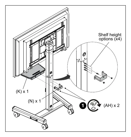
The included shelf assembly (K) can be installed at four different heights on the lower column (Q). Secure it to the front of the column using one stud connector (N) and two 5/16-18" hex nuts (AH).
Cable Management
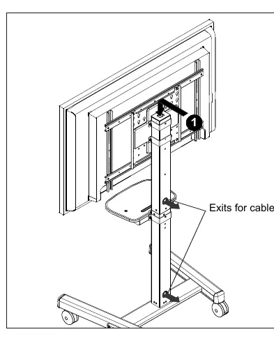
Route the display power cord and signal cables through the top of the post and down through the center to exit out the back of the cart. This keeps cables organized and prevents tripping hazards.
Safety and Maintenance
- Weight Limits: Do not exceed 175 lbs for the display or 10 lbs for the shelf.
- Moving the Cart: Always push the cart near the middle, never at the top. Move slowly and only on level surfaces.
- Children Safety: Do not allow children under 16 to move the cart. Do not place toys or remote controls on the cart as this may encourage children to climb on it.
- Maintenance: Periodically check and tighten the hex nuts on the casters, especially after use on uneven ground. The cart has no user-serviceable parts.
Manufacturer information
Chief
Practical help
Common problems
Cart instability or tipping
Ensure the cart is on a level surface, wheels are locked, and no toys or remotes are placed on the cart. Never push the cart from the top; always push near the center.
Hardware damage during assembly
Do not use a power drill to insert button head cap screws. Insert and turn by hand with the hex key or a handheld screwdriver first.
Display mounting issues
If the display has a recessed surface or protrusions, use the provided spacers and longer hardware between the display and the interface brackets.
Before use
- Verify display weight is under 175 lbs (79.38 kg).
- Verify display VESA pattern is 800x600 or smaller.
- Ensure the cart is placed on a level surface.
- Lock the wheels when the cart is not moving.
- Check that all screws are tightened securely.
- Ensure cables are routed through the post to prevent snagging.
Specs in practice
- Max Display Weight
- 175 lbs (79.38 kg) - Do not exceed this limit to prevent tipping or collapse.
- Max Shelf Weight
- 10 lbs (4.5 kg) - Limit for accessories like laptops or keyboards.
- Display Size
- Supports displays between 55" and 86".
Images and diagrams
- Figures 1-4 show the step-by-step assembly of the base, columns, and face plate.
- Figures 6-10 illustrate the two methods for attaching the display (with or without interface brackets).
- Figure 17 shows the shelf installation on the lower column.
- Figure 18 demonstrates the cable routing path through the column.
Model compatibility
- Compatible with VESA patterns up to 800x600.
- Interface brackets are required for VESA patterns larger than 400x400.
- Universal spacers (H) are only for use in the two uppermost mounting holes.

Manual page author
Michael Turner
Technical manual editor
Reviews PDF manuals for structure, safety notes, and practical product details so readers can find the right information quickly.