Accessories / Mounts & Stands
Installation Instructions for Chief VCT XL Projector Mount and HCU Interface Bracket
A comprehensive installation and adjustment guide for the Chief VCT XL Projector Mount and HCU Interface Bracket. This guide covers mounting the VCT to a pipe, attaching the HCU interface bracket to a projector, and performing fine-tune...
Table of contents
Manual images
Click an image to enlargeQuick Guide from the Manual
The Chief VCT XL Projector Mount is designed for professional projector installations. Important Safety Requirements:
- Weight Capacity: The combined weight of all components must not exceed 150 lbs (68.0 kg).
- Structural Strength: The mounting structure must support five times the combined weight of all equipment.
- Pipe Requirement: Must be mounted to a 1-1/2" NPT or NPSM (Schedule 40, 0.154" minimum thickness steel or aluminum) threaded extension column.
- Environment: For indoor use only.
Installation: VCT Mount to Extension Column
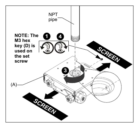
- Loosen and remove the set screw from the VCT mount.
- Thread the VCT mount onto the existing 1-1/2" NPT pipe until tight, ensuring at least four threads are engaged.
- Ensure the side of the VCT mount with two knobs is parallel to or opposite the screen.
- Tighten the set screw into the threaded collar to prevent movement.
Installation: HCU Interface Bracket to Projector
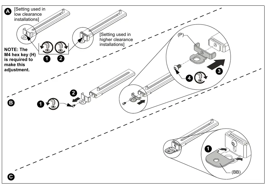
- Maneuver the interface legs on top of the projector so that sliding stud brackets are positioned towards the middle of the projector.
- Ensure the attachment points are located over threaded holes in the projector.
- Select the correct screws and spacers from the hardware kit.
- Attach the legs to the projector. A minimum of four legs must be used.
- Position the sliding stud brackets so the interface assembly can be mounted evenly.
- Place the interface assembly over the sliding stud brackets and fasten using M8 flanged nuts.
Installing Projector to VCT Mount
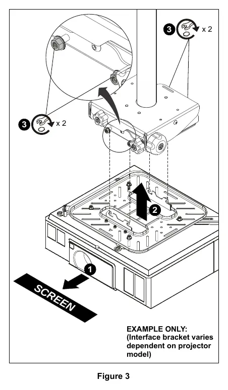
- Orient the projector with the attached interface bracket so it is square to the screen.
- Lift the projector and install it behind the flange nuts on the four studs extending from the VCT housing.
- Ensure the interface bracket hooks are seated on the studs.
- Tighten the flange nuts on the four studs.
Adjustments
The VCT mount allows for precise projector alignment:
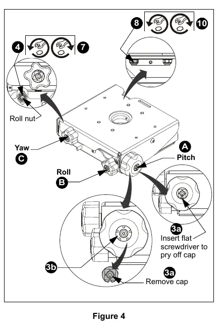
- Pitch: Turn the PITCH knob to tilt the projector up or down. For large adjustments, remove the center cap, insert the pitch socket adapter, and use a drill with an M13 socket.
- Roll: Loosen the Roll nut, turn the ROLL knob to adjust side-to-side tilt, then retighten the Roll nut.
- Yaw: Loosen the Yaw nut, rotate the mount around the column as required, then retighten the Yaw nut.
Manufacturer information
Chief
Practical help
Common problems
Projector falling
Ensure the interface bracket hooks are fully seated on the VCT mount studs and all flange nuts are tightened.
Mount movement
Ensure the set screw on the VCT mount threaded collar is tightened securely against the pipe.
Difficulty adjusting pitch
For large pitch adjustments, use the included pitch socket adapter with an M13 socket drill attachment.
Before use
- Verify the mounting structure can support 5x the total equipment weight.
- Ensure the extension column is 1-1/2" NPT or NPSM (Schedule 40).
- Confirm the combined weight of components does not exceed 150 lbs (68 kg).
- Check that a minimum of four interface legs are used for the projector.
- Ensure the VCT mount set screw is installed and tightened.
Images and diagrams
- Figure 1 (VCT): Shows the VCT mount attaching to the NPT pipe and the location of the set screw.
- Figure 3 (HCU): Illustrates how to mount the projector with the interface bracket onto the VCT housing.
- Figure 4 (Adjustments): Identifies the location of Pitch, Roll, and Yaw knobs and nuts.
Model compatibility
- VCT mount uses Chief 'HC' Series interface brackets.
- HCU interface bracket is compatible with Chief model VCT000.
- Nested washer (BB) must be used when using M4, M5, or M6 attachment screws.

Manual page author
Emily Carter
User documentation editor
Prepares concise manual descriptions and highlights the most useful setup, operation, and maintenance information for readers.