Music / Music Accessories
User Manual for Chord NU1 Dual UHF Wireless System
Quick guide for the Chord NU1 Dual UHF Wireless System. Includes setup instructions, operation steps, troubleshooting, and technical specifications for models 171.981UK, 171.982UK, 171.983UK, and 171.984UK.
Quick answers from the manual
Quick answer
- The Chord NU1 is a UHF wireless microphone system. Setup involves inserting batteries into the transmitter, connecting the receiver to power and an audio mixer/amplifier, and adjusting volume levels. p. 4
Key actions
- Operation p. 4
First start
- Insert batteries into transmitter, connect power adapter to receiver, connect audio output to mixer/amplifier, turn on. p. 4
Problems and fixes
Power LED does not light
Ensure power adapter is connected to mains and working properly; ensure receiver is switched on.
p. 5Maintenance and reset
- Clean the body of the handheld transmitter and receiver with a soft cloth and neutral detergent. Use lightly damp sterile wipes for the microphone grille. p. 2
Technical specifications
| Parameter | Value | Meaning | Pages |
|---|---|---|---|
| Power supply | 12 - 18Vdc 350mA | Required power adapter specification | p. 5 |
| Range | 60m (max) | Maximum operating distance | p. 5 |
Where to find it in the PDF
- Introduction and Safety p. 2
- Diagrams p. 3
- Setup and Operation p. 4
- Specifications and Troubleshooting p. 5
Table of contents
Manual images
Click an image to enlargeQuick Guide
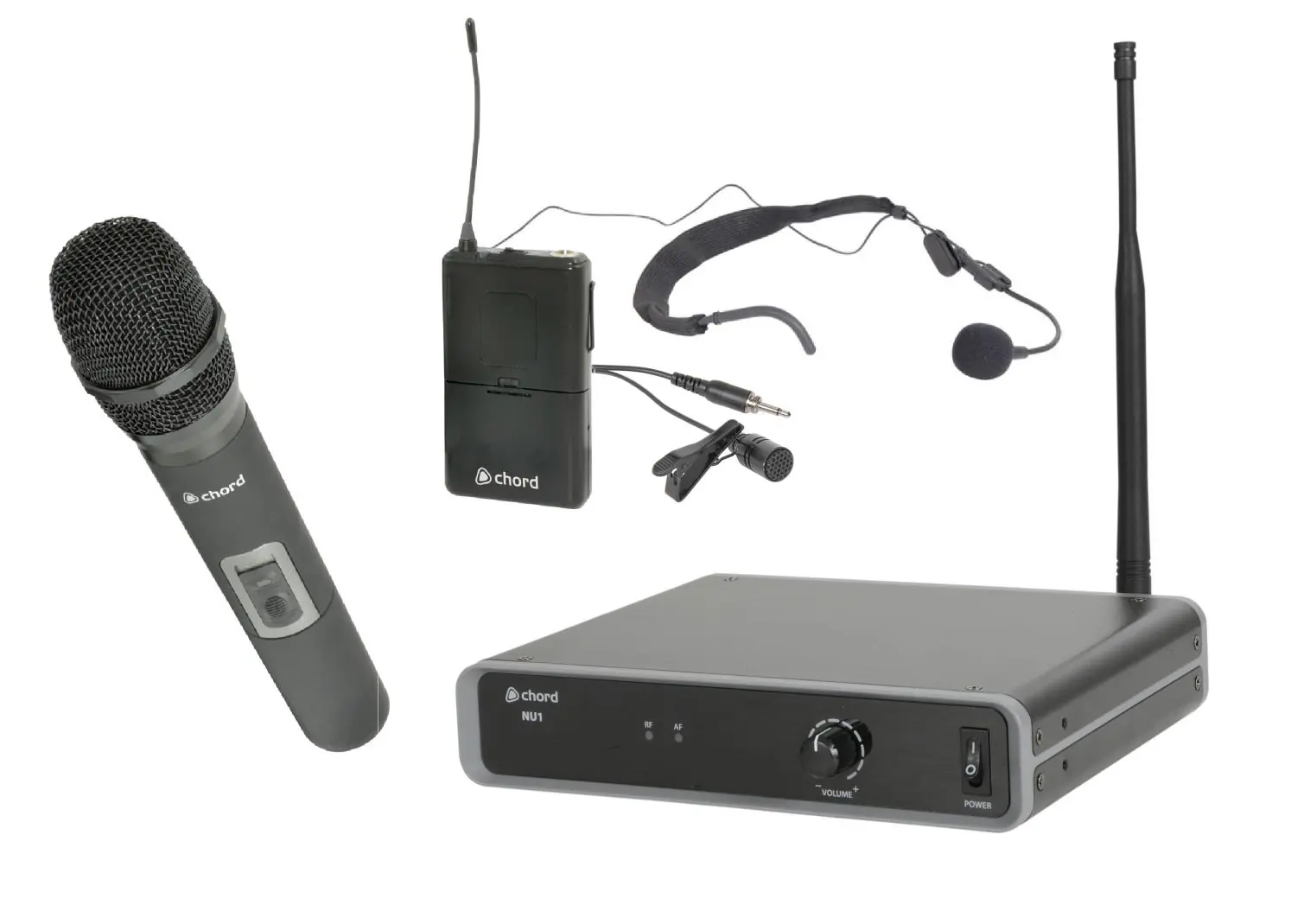
The Chord NU1 is a professional UHF wireless microphone system designed for freedom of movement. This guide covers the setup and operation of the receiver and transmitter units. Ensure you read the safety warnings regarding moisture and power supply before use.
Safety and Placement
- Keep all components away from direct sunlight, heat sources, damp, or dusty environments.
- Do not place heavy objects on top of the receiver or transmitters.
- Ensure the correct power adapter (350mA minimum) is used with the correct mains voltage.
- Use alkaline or NiMH batteries in the transmitters and remove them if the system is not used for long periods.
- Avoid dropping the microphone to prevent capsule failure.
Receiver and Transmitter Overview
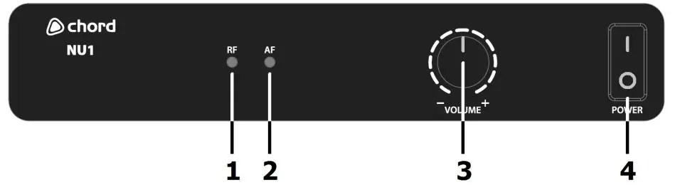
The receiver features an RF carrier signal indicator, AF audio signal indicator, volume control, and power switch on the front panel. The rear panel includes the BNC antenna connector, balanced XLRM output, unbalanced 6.3mm jack output, and DC power input.
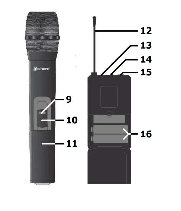
The transmitters (handheld or bodypack) feature an on/off switch, battery compartment, and antenna. Bodypack transmitters also include a 3.5mm threaded jack socket for the microphone input.
Setting Up
- Batteries: Insert fresh AA batteries into the transmitter, ensuring correct polarity.
- Receiver Placement: Position the receiver within line of sight of the transmitter.
- Power: Connect the supplied power adapter to the receiver and the mains outlet.
- Antenna: Connect the aerial to the BNC connector on the rear panel.
- Audio Connection: Connect the receiver to your mixer or amplifier using either the balanced XLR or unbalanced 6.3mm jack output. Turn down the volume on your audio equipment before connecting.
Operation
Switch on the receiver. Move the transmitter switch to the ON position. Gradually increase the microphone level on the receiver, then adjust the volume on your mixer or amplifier until the sound is audible. After use, switch the transmitter to OFF to mute and deactivate the signal, then power down the receiver.
Troubleshooting
If the system is not working, check the following:
- Power LED does not light: Ensure the power adapter is connected and the receiver is switched on.
- Power LED is lit but no RF/AF: Ensure the transmitter is switched on, within range, and has charged batteries.
- No sound: Check that the receiver is connected to the mixer/amplifier and that volume levels are turned up.
- Distorted output: Turn down the volume on the receiver or reduce gain on the mixer/amplifier.
Specifications
The system operates at 863.1MHz or 864.1MHz depending on the model. It features a signal-to-noise ratio of >105dB, a maximum range of 60m, and a THD of <0.5% at 1kHz. The receiver requires a 12-18Vdc 350mA power supply.
Manufacturer information
Chord
Practical help
Common problems
Power LED does not light on receiver
Ensure the power adapter is connected to the mains and the receiver is switched on.
Power LED is lit but no RF or AF LEDs
Ensure the transmitter is switched on, within reception range, and has charged batteries.
All LEDs lit but no sound from mic
Make sure the receiver is connected to the mixer/amplifier and that volume levels are turned up.
Microphone output is very loud or distorted
Turn down the VOLUME on the receiver and reduce gain on the mixer/amplifier.
Before use
- Ensure the correct power adapter (350mA minimum) is used.
- Insert fresh AA batteries into the transmitter, checking polarity.
- Connect the antenna to the BNC connector on the rear panel.
- Turn down the microphone level on the receiver before connecting to audio equipment.
- Ensure the transmitter is within line of sight of the receiver.
Specs in practice
- Carrier frequency
- The operating frequency of the system (863.1MHz or 864.1MHz).
Images and diagrams
- Receiver Front Panel: Shows signal indicators (RF/AF), volume control, and power switch.
- Receiver Rear Panel: Shows antenna connection, balanced XLR output, unbalanced jack output, and DC power input.
- Transmitters: Shows battery compartment, on/off switch, and antenna location.
Model compatibility
- Replacement transmitters must be genuine Chord branded transmitters with the correct pilot tone.
- Transmitters with the same carrier frequency but incorrect pilot tone will not work.

Manual page author
Emily Carter
User documentation editor
Prepares concise manual descriptions and highlights the most useful setup, operation, and maintenance information for readers.