Electronics / Microphones
User Manual for Chord NU2 Dual UHF Wireless System
Quick guide for the Chord NU2 Dual UHF Wireless System. Learn how to set up, operate, and troubleshoot your wireless microphone system, including battery installation and connection instructions.
Quick answers from the manual
Quick answer
- The Chord NU2 is a dual UHF wireless microphone system. To operate, install AA batteries in the transmitters, connect the receiver to power and your audio equipment (mixer/amplifier), and ensure a clear line of sight between the transmitters and the receiver. p. 2, 4
Key actions
- Install batteries in handheld transmitter p. 4
- Install batteries in bodypack transmitter p. 4
- Connect to audio equipment p. 4
First start
- Power on receiver and transmitters p. 4
Problems and fixes
All LEDs lit but no sound from mic
Make sure receiver is connected to mixer/amplifier and volumes are turned up.
p. 5Maintenance and reset
- Cleaning p. 2
Technical specifications
| Parameter | Value | Meaning | Pages |
|---|---|---|---|
| RF power | 10mW | Radio frequency transmission power. | p. 5 |
| S/N ratio | >96dB | Signal-to-noise ratio. | p. 5 |
Where to find it in the PDF
- Front Cover p. 1
- Introduction and Safety p. 2
- Diagrams p. 3
- Setup and Operation p. 4
- Specifications and Troubleshooting p. 5
Table of contents
Manual images
Click an image to enlargeQuick guide from the manual
The Chord NU2 is a professional dual UHF wireless microphone system. To get started, ensure you have the correct power adapter (350mA minimum) and fresh AA batteries for the transmitters. Maintain a clear line of sight between the transmitters and the receiver for optimal performance. Always turn down the volume on your mixer or amplifier before connecting or disconnecting the system to prevent loud feedback or damage.
Package Contents
- NU2 dual UHF wireless receiver
- 19 inch rack ears
- 2 x UHF aerials
- 2 x BNC antenna cables (for front panel mounting)
- 2 x Transmitters (handheld or bodypack)
- 2 x Neckband and 2 x lavalier microphones (NU2-N only)
- Mains power adapter
- 6.3mm mono jack lead
- 4 x 1.5V AA batteries
Receiver Front Panel
The front panel features controls for both channels:
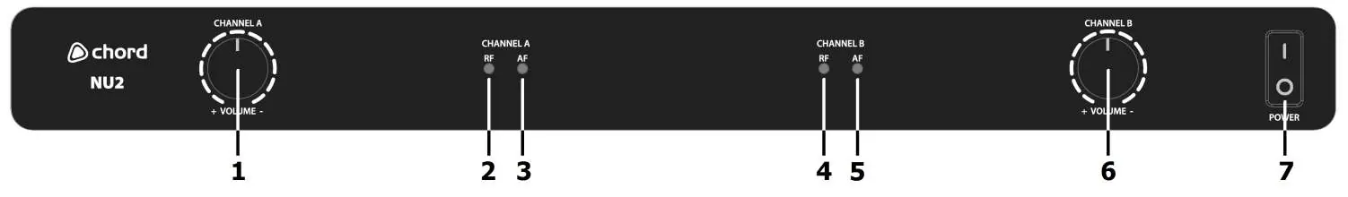
- Volume Control: Adjusts the output level for Channel A and Channel B.
- Indicators: RF carrier signal and AF audio signal indicators for both channels.
- Power Switch: Main power on/off switch.
Receiver Rear Panel
The rear panel provides connectivity options:
- Power Input: DC input for the supplied power adapter.
- Antenna Connectors: BNC connectors for Channel A and Channel B antennas.
- Outputs: Balanced XLRM outputs for each channel and an unbalanced 6.3mm jack mix output.
Transmitters
The system supports handheld or bodypack transmitters:
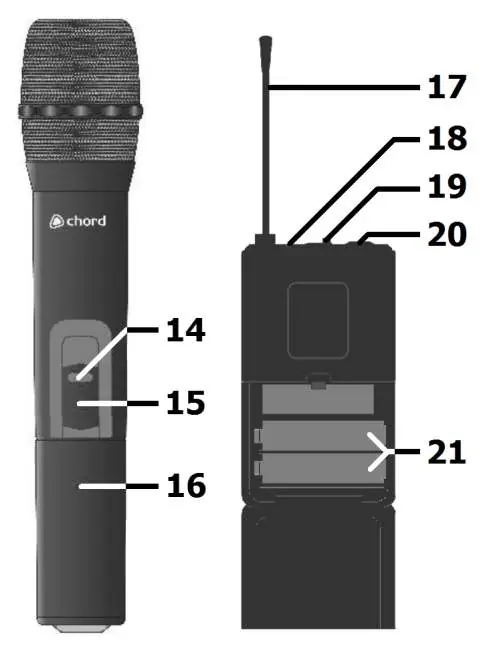
- Handheld: Unscrew the base to access the battery compartment. Features an on/off switch and on indicator.
- Bodypack: Squeeze and flip the front cover to access the battery compartment. Connect the neckband or lavalier microphone to the 3.5mm threaded jack socket.
Operation
Starting the system:
- Switch on the receiver unit.
- Move the transmitter switch to the ON position.
- Gradually increase the microphone level on the receiver.
- Increase the volume on your mixer or amplifier until the sound is audible.
Important usage notes:
- The transmitter slide switch has a MUTE center position, which is not used with the NU-series; switching the transmitter OFF automatically mutes the channel.
- Avoid pointing microphones directly at speakers to prevent feedback (loud whistling).
- Remove batteries if the system will not be used for long periods.
Troubleshooting
- Power LED not lit: Check that the power adapter is connected and the receiver is switched on.
- Power LED lit but no RF/AF: Ensure the transmitter is switched on, within range, and has charged batteries.
- Power and RF lit but no AF/sound: Check that the transmitter switch is on, batteries are good, and there is no interference from other transmitters.
- Distorted sound: Turn down the volume on the receiver or reduce the gain on your mixer/amplifier.
Specifications
- Carrier Frequency: 863.3MHz + 864.3MHz or 863.8MHz + 864.8MHz (depending on model).
- Range: 60m (maximum).
- Power Supply: 12-18Vdc 500mA adapter.
- Output Level: 400mV (balanced), 200mV (unbalanced).
- Weight (Receiver): 1.37kg.
Manufacturer information
Chord
Practical help
Common problems
Power LED does not light on receiver
Ensure the power adapter is connected to the mains and the receiver is switched on.
Power LED is lit but no RF or AF signal
Check that the transmitter is switched on, within range, and has fresh/charged batteries.
Microphone output is distorted
Turn down the volume on the receiver or reduce the gain on the mixer/amplifier. Ensure an XLR output is not fed into a line input.
Microphone output is very low
Turn up the volume on the receiver, increase the mixer/amplifier gain, or check transmitter batteries.
Before use
- Verify all accessories are present.
- Install fresh AA batteries in the transmitters, observing correct polarity.
- Ensure the power adapter used has a minimum 350mA rating.
- Connect antennas to the BNC connectors on the rear panel.
- Turn down microphone levels on the receiver before connecting to audio equipment.
Specs in practice
- Carrier Frequency
- The radio frequency used for transmission; varies by model (863.3/864.3MHz or 863.8/864.8MHz).
- Output Level
- Signal strength: 400mV for balanced XLR outputs, 200mV for unbalanced jack output.
Images and diagrams
- The receiver front panel contains volume controls and signal indicators for both channels.
- The receiver rear panel houses the power input, antenna BNC connectors, and audio outputs (XLR and 6.3mm jack).
- Transmitters feature an on/off switch, battery compartment, and antenna.
Model compatibility
- Replacement transmitters must be genuine Chord branded units with the correct pilot tone.
- Transmitters with the same carrier frequency but incorrect pilot tone will not work.

Manual page author
David Miller
Documentation analyst
Organizes user manual content into clear summaries, with attention to model details, product context, and everyday usability.