Automotive / Garage Equipment
Parts Manual for PEAK 209C and 209CH 2-Post Lift
Comprehensive parts manual and exploded view guide for the PEAK 209C and 209CH 2-post lifts. Includes detailed diagrams and component lists for the lifting arm, cylinders, and hydraulic power unit.
Table of contents
Manual images
Click an image to enlargeQuick guide from the manual
This document serves as a comprehensive parts reference for the PEAK 209C and 209CH 2-post lifts. It provides exploded view diagrams and corresponding parts lists to assist in identifying components for maintenance and repair. Always verify the model number and electrical specifications before ordering replacement parts.
Exploded View and Parts List
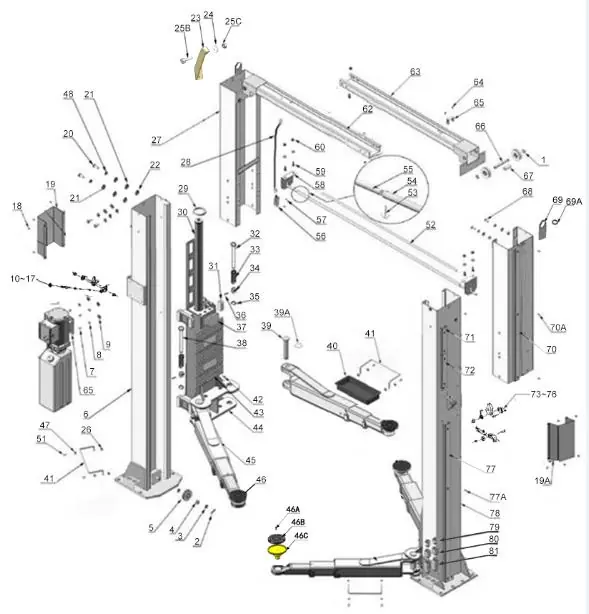
The manual contains detailed exploded views of the entire lift structure (Fig 43) and specific sub-assemblies. The parts lists on pages 25-28 provide the item number, part number, description, and quantity required for both the 209C and 209CH models.
Lifting Arm Assembly
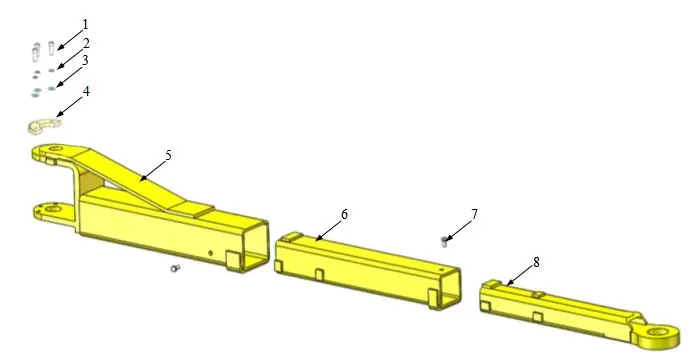
Detailed breakdown of the lifting arm (10203156) is provided in Fig 44, including the socket bolts, washers, moon gear, and arm components.
Cylinder Assembly
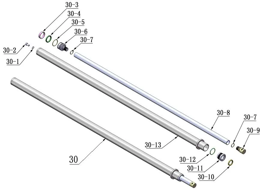
Detailed breakdown of the cylinders (10217056) is provided in Fig 45, including O-rings, pistons, piston rods, and dust rings.
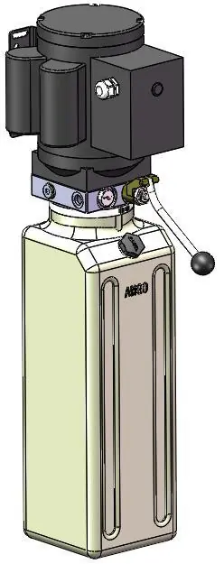
Hydraulic Power Unit
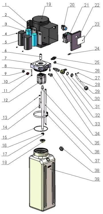
Exploded views and parts lists for the power unit (81513001/81513002) are provided in Fig 46, covering both 220V/50Hz/1phase and 380V/50Hz/3phase configurations. Ensure you reference the correct parts list for your specific electrical setup.
Hydraulic Valve
Fig 47 provides an illustration of the hydraulic valve components, including the release valve, check valve, and relief valve, for the hydraulic power unit.
Practical help
Before use
- Verify model number (209C or 209CH) before ordering parts.
- Consult the exploded view diagrams to identify the correct component.
- Check voltage requirements (220V/1phase vs 380V/3phase) for power unit parts.
Images and diagrams
- Fig 43: Main exploded view of the 2-post lift structure.
- Fig 44: Detailed view of the lifting arm assembly.
- Fig 45: Cylinder component breakdown.
- Fig 46: Power unit exploded view for different electrical configurations.
- Fig 47: Hydraulic valve illustration.
Model compatibility
- Parts lists distinguish between 209C and 209CH models where applicable.
- Power unit parts vary based on electrical configuration (220V/1phase vs 380V/3phase).

Manual page author
Michael Turner
Technical manual editor
Reviews PDF manuals for structure, safety notes, and practical product details so readers can find the right information quickly.