Automotive / Garage Equipment
User Manual for Tradequip 2063T 1,000 KG Transmission Lifter
Quick guide for the Tradequip 2063T 1,000 KG Transmission Lifter. Includes assembly instructions, safe operating procedures, maintenance tips, and troubleshooting steps.
Quick answers from the manual
Quick answer
- The Tradequip 2063T is a 1,000kg capacity transmission lifter. Always open the breather valve before use, bleed the hydraulic system, and ensure the load is centered on the saddle. p. 1, 4
Key actions
- Bleeding the hydraulic system p. 4
- Lubricating the lifter p. 6
First start
- Initial setup and bleeding p. 4
Problems and fixes
Lifter will not lift
Bleed system, check for air, or reset pump circuit protection valve.
p. 7Maintenance and reset
- Resetting pump circuit protection valve p. 7
Technical specifications
| Parameter | Value | Meaning | Pages |
|---|---|---|---|
| Rated Capacity | 1000kg | Maximum lifting capacity | p. 1 |
| Lift Range | 950-1930mm | Vertical lift height | p. 1 |
Where to find it in the PDF
- Specifications p. 1
- Assembly p. 4
- Troubleshooting p. 7
Table of contents
Manual images
Click an image to enlargeQuick guide from the manual
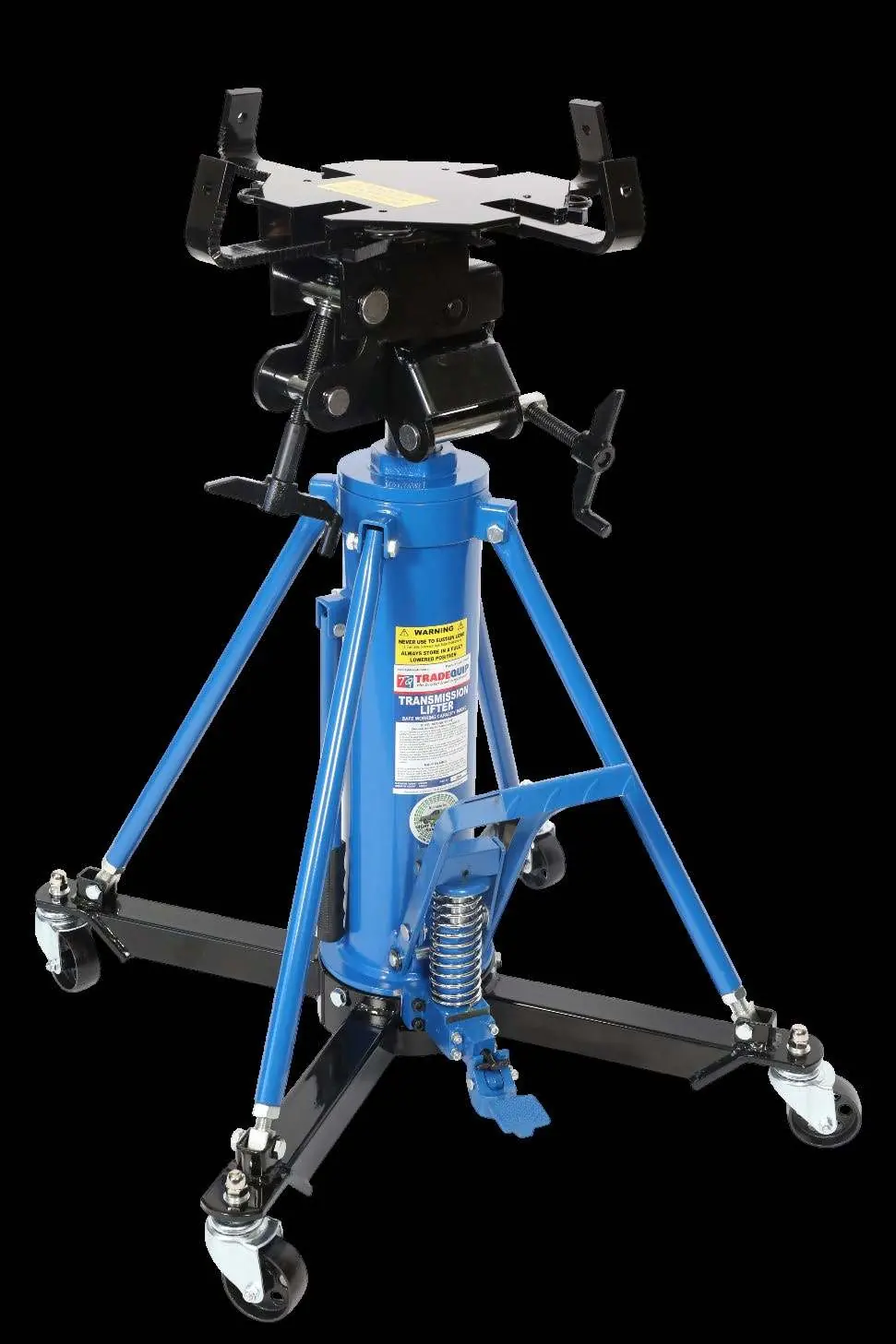
The Tradequip 2063T is a 1,000kg capacity telescopic transmission lifter designed for the removal, installation, and transportation of passenger vehicle transmissions. Important: Always open the breather valve before use, ensure the load is centered on the saddle, and bleed the hydraulic system before the first operation.
Safety Precautions
- Do not exceed the 1,000kg load capacity.
- Use only on a stable, level, smooth, and dry surface.
- Vehicle must be properly supported before using the lifter.
- Always wear safety glasses, non-skid boots, and heavy-duty work gloves.
- Do not use the lifter to support loads; transfer the load immediately to an appropriate support device.
- Do not tamper with the safety valve.
Assembly
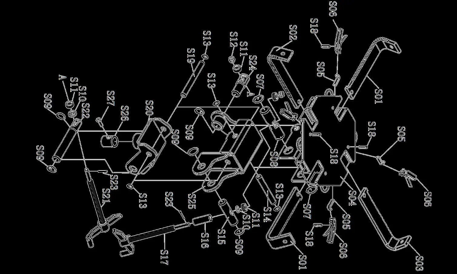
Unpack the product and verify all parts against the parts list. Assembly steps:

- Attach leg assemblies together using bolts, washers, lock washers, and nuts. Turn upright and attach the four castors.
- Mount the jack main body onto the center of the legs and tighten with washers, lock washers, and bolts.
- Attach mounting brackets to the main body.
- Attach side supports to the mounting bracket and leg assembly.
- Screw the saddle kit onto the top of the piston rod and assemble the adaptor.
Before Use
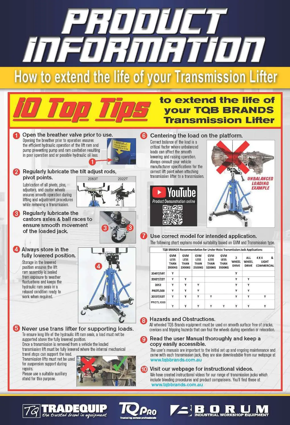
Ensure the breather valve is open. Before the first use, leave the jack for one hour to allow oil to settle. Bleed the hydraulic system by pushing down the foot-operated release pedal and pumping the lift pedal 15-20 times to remove trapped air. Test the jack without a load by raising it to full height and lowering it.
Operation
- Loosen the air vent screw before use.
- Roll the lifter into position and pump the lift pedal to reach the desired height.
- Center the load on the saddle and secure it with chains.
- To lower, slowly and carefully push the release foot pedal. The speed of descent is controlled by the pressure on the release valve.
- Once lowered, move the lifter carefully and transfer the load to a support device.
- Lower the saddle fully and tighten the air vent screw after work is complete.
Maintenance
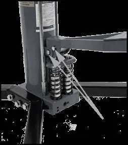
- Lubrication: Periodically lubricate pivots, pins, wheel axles, and castor ball races with light bearing grease or 30/40W machine oil.
- Cleaning: Keep the lifter clean and free of dirt. Do not use a pressure washer near seals, pistons, or valves.
- Oil Level: If the lifter fades under load, check the oil level. With the lifter in the lowest position, remove the oil filler plug; oil should be at the bottom of the hole. Use ISO VG32 hydraulic oil.
Troubleshooting
If the lifter fails to operate correctly, check for air in the system (bleed it), ensure the breather valve is open, or check for fluid levels. If the lifter will not hold a load, the release valve may be misaligned or seals may be damaged.
Specifications
- Rated Capacity: 1,000kg
- Lift Range: 950-1930mm
- Tilt: 11° forward/rearward, 9-11° side
- Gross Weight: 82.5kg
Manufacturer information
TradeQuip
Practical help
Common problems
Lifter will not lift using foot pump
Check for air in the hydraulic system and bleed it. Ensure fasteners are tight. If the pump circuit protection valve is actuated, depress the release pedal to reset.
Lifter will not hold load
The release valve may be unable to close due to misalignment, or there may be an external leak. Contact a qualified technician.
Lifter will not lower
The reservoir may be overfilled and the breather closed, causing hydraulic lock. Open the breather and bleed the system.
Before use
- Check for abnormal conditions like cracked welds, leaks, or loose parts.
- Ensure the breather valve is open.
- Bleed the hydraulic system if the unit has been stored or moved.
- Ensure the surface is stable, level, and capable of sustaining the load.
- Verify the vehicle is properly supported.
Specs in practice
- Rated Capacity
- Maximum load the lifter can safely handle (1,000kg).
Images and diagrams
- Exploded view of the main body and leg assembly for proper installation.
- Detailed parts drawing for the saddle and mounting components.
- Lubrication points for pivots, pins, and castor assemblies.
Model compatibility
- Suitable for RWD/FWD/AWD/4X4 vehicles with GVM < 3,200kg.
- Not designed for supporting loads; transfer to a support device immediately.

Manual page author
Michael Turner
Technical manual editor
Reviews PDF manuals for structure, safety notes, and practical product details so readers can find the right information quickly.