Electronics / Amplifiers Receivers
Installation and User Guide for Cloud 46 Series Mixer-Amplifiers
Comprehensive installation and user guide for Cloud 46-120MK2 and 46-240 four-zone mixer-amplifiers. Includes detailed instructions on wiring, configuration, remote control setup, and troubleshooting.
Table of contents
Manual images
Click an image to enlargeQuick guide from the manual
The Cloud 46 Series are four-zone mixer-amplifiers designed for commercial venues. Before installation, ensure the unit is placed in a well-ventilated 19-inch rack with at least 100mm of rear clearance. The unit operates on 85-265V AC mains. Always configure the speaker output type (Lo-Z or Hi-Z) and impedance using the rear panel DIP switches before connecting speakers. The unit features automatic power-down, music mute for fire alarms, and support for various remote control modules.
Overview
The 46 Series includes two models: the 46-120MK2 (4 x 120W) and the 46-240 (4 x 240W). Both models provide per-zone control for music source, music level, and microphone levels. They support balanced line inputs, microphone inputs with phantom power, and various remote control options via Facility Ports and Remote Music Control Ports.
Installation
The unit is a 2U rack-mount device. Ensure the ambient temperature remains between 0°C and 35°C. Air intake is at the front and exhaust is at the rear; do not block these vents. If using free-standing, attach the supplied plastic feet. The internal power supply is universal. The only externally accessible fuse is the AC mains fuse located near the IEC receptacle; replace only with the exact type specified (T5AH 250V for 46-120MK2, T8AH 250V for 46-240).
Connections and Controls
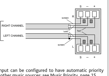
The unit features six stereo line inputs (two unbalanced RCA, four balanced screw-terminal). Microphone inputs are balanced with 12V phantom power available. Speaker outputs support both low-impedance (4 or 8 ohms) and 70/100V line systems. Remote control plates (RL-1, RSL-6) can be connected to the Remote Music Control Ports. Facility Ports support active modules like LM-2 or BT-1. A Music Mute input is provided for emergency system integration.
Configuration
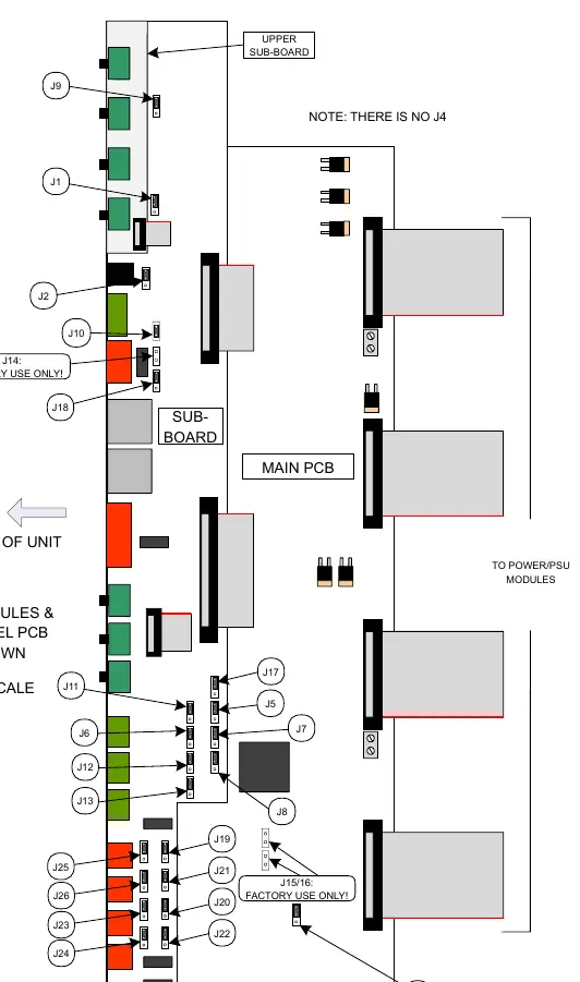
Configuration is handled via rear panel DIP switches and internal PCB jumpers. Rear DIP switches control speaker output settings (filter, impedance, Hi-Z/Lo-Z) and remote control assignment. Internal jumpers allow for advanced routing, such as Line 6 priority, Facility Port routing, and auxiliary output source selection. Always disconnect from mains power before opening the unit to adjust internal jumpers.
Troubleshooting
Status LED indications: Off (Power off), Green (Normal), Red (Standby/APD), Flashing Green (Power reduction due to high temperature), Flashing Red (Fault condition/outputs muted). If the unit enters protection mode (flashing red), check for short circuits, over-current, or DC at the output terminals. Ensure ventilation is adequate if the unit is overheating.
Technical Specifications
Frequency response is 20Hz to 20kHz. Line input sensitivity ranges from 195mV to 2.0V. Microphone input impedance is 3.3 kohms. The unit features fixed-level signal limiters and thermal protection. Power consumption varies by model and load, with standby power under 10W.
Practical help
Common problems
Status LED flashing green
Output power is reduced due to high temperature. Improve ventilation and reduce input signal levels.
Status LED flashing red
Over-temperature shutdown or amplifier protection triggered. Check for short circuits, over-current, or DC at output terminals.
No sound from a zone
Check if the zone is in Standby (APD) mode, check speaker wiring, or verify if Music Mute is active.
Before use
- Ensure ventilation slots are clear of obstructions.
- Verify mains voltage is within 85V-265V range.
- Set speaker output DIP switches correctly for your load (Lo-Z or Hi-Z).
- Ensure correct speaker impedance (4/8 ohm or 70/100V) is selected.
- Check that all remote control plates are wired correctly.
Specs in practice
- Output Power
- 120W or 240W per zone depending on model; 46-120MK2 supports power sharing.
- Frequency Response
- 20Hz to 20kHz (+/- 1dB), ensuring full-range audio reproduction.
- Phantom Power
- 12V available on mic inputs, switchable via internal jumpers.
Images and diagrams
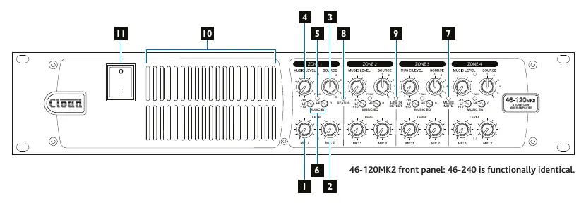
- Front panel: Controls for Mic levels, Music source, Music level, and status LEDs.
- Rear panel: Inputs, outputs, DIP switches for configuration, and power connection.
- Speaker wiring: Diagrams show connections for 4 ohm, 8 ohm, and 70/100V line systems.
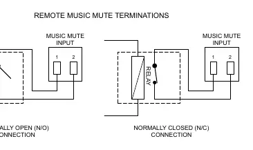
- Music Mute: Wiring for N/O or N/C relay connections.
Model compatibility
- Compatible with Cloud PM series paging microphones.
- Compatible with RL-1 and RSL-6 remote control plates.
- Supports LM-2, BT-1, L-1, and M-1 active remote modules.
- BT-1 must be the BT-1F variant.

Manual page author
Michael Turner
Technical manual editor
Reviews PDF manuals for structure, safety notes, and practical product details so readers can find the right information quickly.