Home Appliances / Washing Machines
Crown Amplifier Application Guide
A comprehensive application guide for Crown amplifiers, covering rack installation, system wiring, gain structure, troubleshooting, and distributed speaker systems.
Table of contents
Manual images
Click an image to enlargeQuick guide from the manual
This application guide provides essential information for the installation, operation, and maintenance of Crown amplifiers. It is designed to complement your specific amplifier's Operation Manual. Key topics include rack cooling techniques, system wiring, gain structure, and troubleshooting procedures.
Rack Cooling
Proper thermal management is critical for amplifier performance. When installing in a rack:
- Fan-Assisted Models: Ensure front vents and filters are not blocked. Clean foam filters with mild detergent and water.
- Convection-Only Models: Leave at least one rack-space between amplifiers to allow heat radiation.
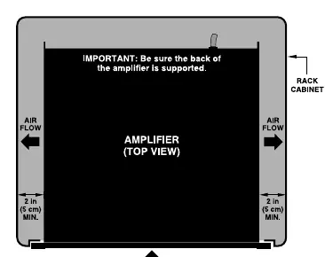
- General Guidelines: Maintain at least 2 inches (5 cm) of clearance from side walls for side-venting models. Avoid using vented spacer panels; solid panels are preferred if spacing is required.
- Overheating Causes: Insufficient air movement, overdriving the input stage, very low-impedance loads, or high ambient temperatures.
System Wiring
Correct wiring is essential for signal integrity and noise reduction.

- Input Wiring: Use shielded wire. Avoid running low-level input cables, high-level output wires, and AC power feeds in the same path. Cross signal cables at 90-degree angles to minimize hum and crosstalk.
- Balanced vs. Unbalanced: Balanced lines are recommended for professional applications to reject noise, especially for cable runs over 10 feet (3 meters).
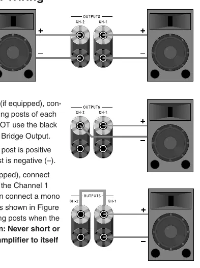
- Output Wiring: Ensure proper connection for Stereo, Bridge-Mono, or Parallel-Mono modes using 5-way binding posts, barrier blocks, or Neutrik Speakon connectors. Never short or parallel output channels to themselves or other amplifiers.
Troubleshooting
The manual provides flowcharts to assist in diagnosing system issues:
- No Power: Check AC source, power switch, and fuses/circuit breakers.
- No Sound: Verify signal source, level controls, speaker connections, and check for short circuits or protection indicators (Fault, TLC, ODEP).
- Bad Sound: Check for clipping, input/output connections, and ground loops.
- Overheating: Inspect filters, ensure adequate airflow, and verify load impedance.
Gain Structure
Setting up your system's gain structure correctly ensures maximum headroom and minimum noise. Start at the front of the system (mixer) and work toward the amplifier. Adjust mixer channels and master levels to 0 dB, then set amplifier level controls to achieve the desired loudness without clipping.
Distributed Speaker Systems
For paging and background music, distributed speaker systems use transformers to step down line voltage. This allows multiple speakers to be connected to a single amplifier channel over long distances using smaller gauge wire.
Glossary of Terms
The manual includes a comprehensive glossary defining technical terms such as Amperage, Amplifier Class, Attenuation, Balanced Line, Bridge-Mono, Clipping, Crossover, Damping Factor, Impedance, ODEP, and Slew Rate.
Practical help
Common problems
Amplifier overheating
Check for insufficient air movement, overdriving the input stage, very low-impedance loads, or high ambient temperatures.
No power
Ensure the unit is plugged into an active AC source, the power switch is on, and check for tripped circuit breakers or blown fuses.
No sound
Check signal source, turn up level controls, ensure speakers are connected, and check for short circuits on the speaker line.
Hum or buzz
Check for ground loops, ensure cable connections are secure, and verify if the source is balanced or unbalanced.
Before use
- Ensure adequate rack ventilation with at least 2 inches of side clearance.
- Verify if your input source is balanced or unbalanced.
- Check speaker impedance compatibility.
- Ensure speaker wire gauge is appropriate for the cable length.
- Turn amplifier level controls down before changing connections.
Specs in practice
- Damping Factor
- Indicator of how tightly the amplifier controls speaker movement; higher is generally better.
Images and diagrams
- Wiring diagrams for balanced and unbalanced input connections.
- Output connector wiring diagrams for Stereo, Bridge-Mono, and Parallel-Mono modes.
- Troubleshooting flowcharts for power, sound, and overheating issues.
- Rack cooling diagrams showing airflow requirements.
Model compatibility
- Compatible with PIP (Programmable Input Processor) modules.
- Supports 70V/100V distributed speaker systems.

Manual page author
David Miller
Documentation analyst
Organizes user manual content into clear summaries, with attention to model details, product context, and everyday usability.