Electronics / Amplifiers Receivers
User Manual for Sonance PowerZone Connect Amplifiers
Quick guide for Sonance PowerZone Connect amplifiers. Covers installation, network configuration, input/output setup, GPIO connections, and operational status indicators.
Table of contents
Manual images
Click an image to enlargeQuick Guide from the Manual
The Sonance PowerZone Connect series are 1U power amplifiers designed for residential and commercial audio applications. These units feature automatic power sharing, network-based configuration via the PowerZone Control web interface, and support for both low-impedance (Lo-Z) and high-impedance (Hi-Z) loudspeakers. The amplifiers have no physical power switch and become operational as soon as mains power is connected.
Installation
Amplifiers are available in half-rack and full-rack widths. Ensure proper ventilation is maintained at all times.
- Ventilation: Maintain at least 25 mm (1 in) of airflow space along at least one side of the amplifier. Retain at least 80 mm (3.1 in) of free space behind the rear panel.
- Rack Mounting: Half-rack models require accessory rack ears and extension pieces. Full-rack models are supplied with rack ears fitted.
- Rear Support: Optional rear support hardware is recommended for mobile racks or environments subject to movement.
Configuration
Configuration is performed via the PowerZone Control web interface. Connect the amplifier to the same TCP/IP network as your computer or mobile device.
- Network Connection: Connect an Ethernet cable to the rear panel Network Control socket. Wait for the front panel Network indicator to illuminate green.
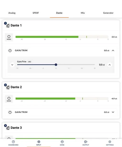
- Input Setup: Use the Input Tab to name inputs, select mono/stereo, adjust sensitivity (+14dB, +4dB, -10dB, or microphone), and apply EQ.
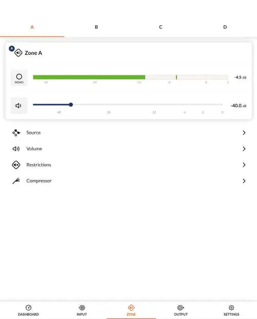
- Zone Setup: Use the Zone Tab to define and name zones (e.g., bar, restaurant, rooms).
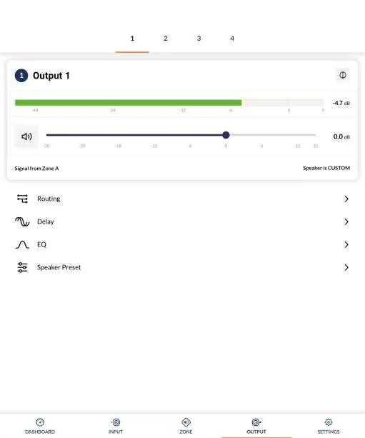
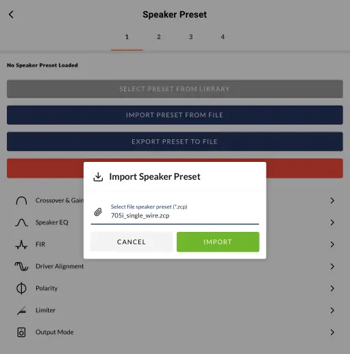
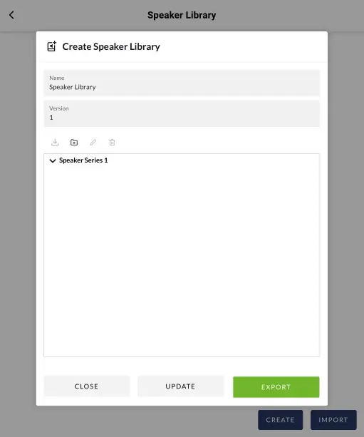
- Output Setup: Use the Output Tab to link outputs to zones, configure delay, room equalization, and manage speaker presets.
Connections
- Inputs: Balanced inputs use Euroblock connectors; unbalanced inputs use RCA phono sockets.
- GPIO: The GPIO socket allows remote control of volume, standby, mute, and trigger functions. Use shielded cable for standby switches and potentiometers.
- Dante: Half-rack width models are optionally compatible with Audinate Dante audio over IP. Configuration is managed via Dante Controller software.
Operation
The amplifier enters operational mode when an input signal above -60dB is present. If no signal is detected for 5 minutes, outputs mute; after 15 minutes of no signal, the unit enters Standby Mode.
- Status Indicator: Off (Mains disconnected), Green (Operational), Pulse Green (Standby), Amber (GPIO triggered Standby).
- Input Indicator: Off (No input signal).
Practical help
Common problems
Amplifier does not switch on from Standby
Ensure an input signal is present, a network 'ON' command is received, or an external standby switch/12V trigger is operated.
No audio output
Check if the input signal is present and above -60dB. Verify that the mix inputs are not muted (default setting) and level sliders are adjusted.
Network configuration not accessible
Ensure the amplifier is connected to the same TCP/IP network as the configuration device. Check the Network indicator on the front panel.
Audible hum
Use the 'soft ground' connection on GPIO Pin 3 to manage ground loops.
Before use
- Verify mains power is connected (100V-240V AC).
- Ensure network connection is established for configuration.
- Check speaker impedance requirements (Lo-Z 4-16 Ohm or Hi-Z 70V/100V).
- Configure output format in the web interface before connecting speakers.
- Ensure all signal, GPIO, and output connections are made before applying mains power.
Images and diagrams
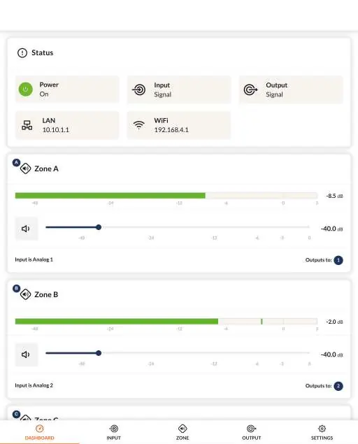
- Diagram 6A: Configuration Dashboard showing status and zone levels.
- Diagram 6B: Input Tab for sensitivity and EQ settings.
- Diagram 6F: Zone Tab for routing and volume control.
- Diagram 6H: Output Tab for speaker presets and routing.
- Diagram 7A/7B: Rear panel connection layouts.
Model compatibility
- Only dynamic microphones are suitable for connection; phantom power is not provided.
- Dante compatibility is optional and limited to half-rack width models.
- FIR coefficient files must be in .csv or .txt format.

Manual page author
David Miller
Documentation analyst
Organizes user manual content into clear summaries, with attention to model details, product context, and everyday usability.