Home Appliances / Commercial Kitchen Equipment
Parts Manual for CMA 180/180TALL Commercial Dishwasher
Comprehensive parts manual for the CMA 180 and 180TALL commercial dishwashers. Includes detailed exploded view diagrams, part numbers, conversion kit instructions, and maintenance procedures for heaters and switches.
Quick answers from the manual
Quick answer
- This document is a parts manual for the CMA 180 and 180TALL commercial dishwashers. It provides exploded view diagrams, part numbers, and instructions for conversion kits and specific component replacements. p. 1, 2
Key actions
- Replacing the power switch bulb p. 24
- Converting Corner to Straight configuration p. 25
- Converting Straight to Corner configuration p. 26
Problems and fixes
Burnt power switch bulb
Dismount light module, replace bulb (P/N 17421.10), and snap back.
p. 24Where to find it in the PDF
- Table of Contents p. 2
- Exploded View Drawings p. 4, 23
- Conversion Kits p. 25, 26
Table of contents
Manual images
Click an image to enlargeQuick guide from the manual
This document is the official parts manual for the CMA 180 and 180TALL commercial dishwashers. It is designed to help technicians and owners identify specific components for maintenance, repair, and configuration changes. The manual contains detailed exploded view diagrams with corresponding parts lists, as well as specific instructions for conversion kits and minor component replacements.
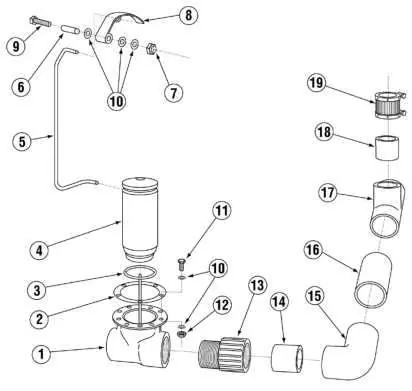
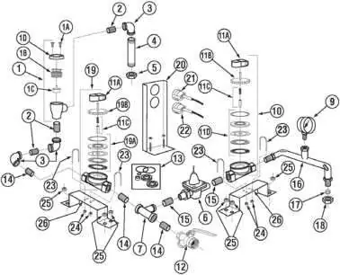
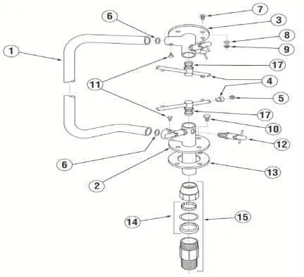
Exploded View Drawings
The core of this manual consists of exploded view drawings for various systems within the dishwasher. Each diagram is accompanied by a table listing the Item Number, Quantity Required, Part Number (P/N), and Description. Key systems covered include:

- Frame Assemblies: Straight and Corner frame configurations.
- Drain System: Components for the drain assembly.
- Plumbing System: Detailed breakdown of water lines, vacuum breakers, and valves.
- Wash Spray System: Manifold and spray arm components.
- Final Rinse System: Rinse plumbing and spray jets.
- Door Handle Assemblies: Mechanisms for standard and corner door configurations.
- Pump System: Motor and seal components.
- Heaters: Both 'Old' (Square Flange) and 'New' (Triangular Flange) styles for Wash Tank and Booster heaters.
- Control Box: Electrical components, fuses, and contactors.
Conversion Kits
The manual provides step-by-step instructions for converting the machine configuration:
- Corner to Straight (#00617.18): Instructions for relocating door hardware and panels.
- Straight to Corner (#00617.17): Instructions for reconfiguring the machine for corner installation.
Maintenance and Replacement
Specific procedures are included for:
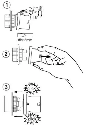
- Power Switch Bulb Replacement: For machines manufactured prior to May 2002, instructions are provided to dismount the light module using a 5mm screwdriver, replace the bulb (P/N 17421.10), and snap the module back into place.
- Drain Water Tempering Valve: Assembly details for the valve (effective 03-2023).
Manufacturer information
CMA Dishmachines
Practical help
Common problems
Burnt power switch bulb
Dismount the light module using a 5mm screwdriver, replace the bulb (P/N 17421.10) by twisting 90 degrees, and snap the module back onto the actuator.
Need to convert machine configuration
Use the specific conversion kits (#00617.18 for Corner to Straight, #00617.17 for Straight to Corner) and follow the detailed installation steps provided in the manual.
Before use
- Verify the exact model number (CMA-180/180TALL) before ordering parts.
- Identify the specific system assembly (e.g., Drain, Plumbing, Wash Spray) requiring service.
- Check if your machine uses the 'Old' or 'New' style heater (Square vs. Triangular Flange).
- Ensure power is disconnected before performing any maintenance or part replacement.
- Consult the exploded view diagrams to ensure all necessary hardware (nuts, bolts, washers) is accounted for.
Images and diagrams
- Exploded views show the assembly order of components.
- Item numbers in diagrams correspond to the parts list tables.
- Dashed lines indicate assembly groupings or specific sub-assemblies.
Model compatibility
- Heater parts differ between 'Old' (Square Flange) and 'New' (Triangular Flange) styles.
- Conversion kits are specific to the direction of change (Corner to Straight vs. Straight to Corner).

Manual page author
Michael Turner
Technical manual editor
Reviews PDF manuals for structure, safety notes, and practical product details so readers can find the right information quickly.