Home Appliances / Commercial Kitchen Equipment
Installation Guide for CMA Dishmachines 180UC-3 Drain Water Tempering Kit
A comprehensive installation guide for the CMA Dishmachines 180UC-3 Drain Water Tempering Kit. Includes factory and field installation procedures, parts identification, and critical water pressure requirements.
Quick answers from the manual
Quick answer
- The Drain Water Tempering Kit for the 180UC-3 dishmachine requires connecting a cold water line to the check valve assembly. The unit must be installed no higher than 12 inches from the floor, and a pressure-reducing valve is required if water pressure exceeds 50 psi. p. 1, 2
Key actions
- Remove the black plug from the valve before connecting the cold water line. p. 1, 2
Technical specifications
| Parameter | Value | Meaning | Pages |
|---|---|---|---|
| Max Height | 12 inches | Maximum height from the floor for the assembly | p. 2 |
| Max Water Pressure | 50 psi | Pressure limit before a reducing valve is required | p. 1 |
Where to find it in the PDF
- Factory Installation Instructions p. 1
- Field Installation Instructions p. 2
- Parts Manual p. 3
Table of contents
Manual images
Click an image to enlargeQuick guide from the manual
The Drain Water Tempering Kit is designed for the 180UC-3 dishmachine. The kit is available as a factory-installed option or as a field-installed kit. The primary function is to temper the drain water. Key installation requirements include ensuring the assembly is no higher than 12 inches from the floor and installing a pressure-reducing valve if the water pressure exceeds 50 psi.
Factory installation
If your machine was shipped with the kit pre-installed:
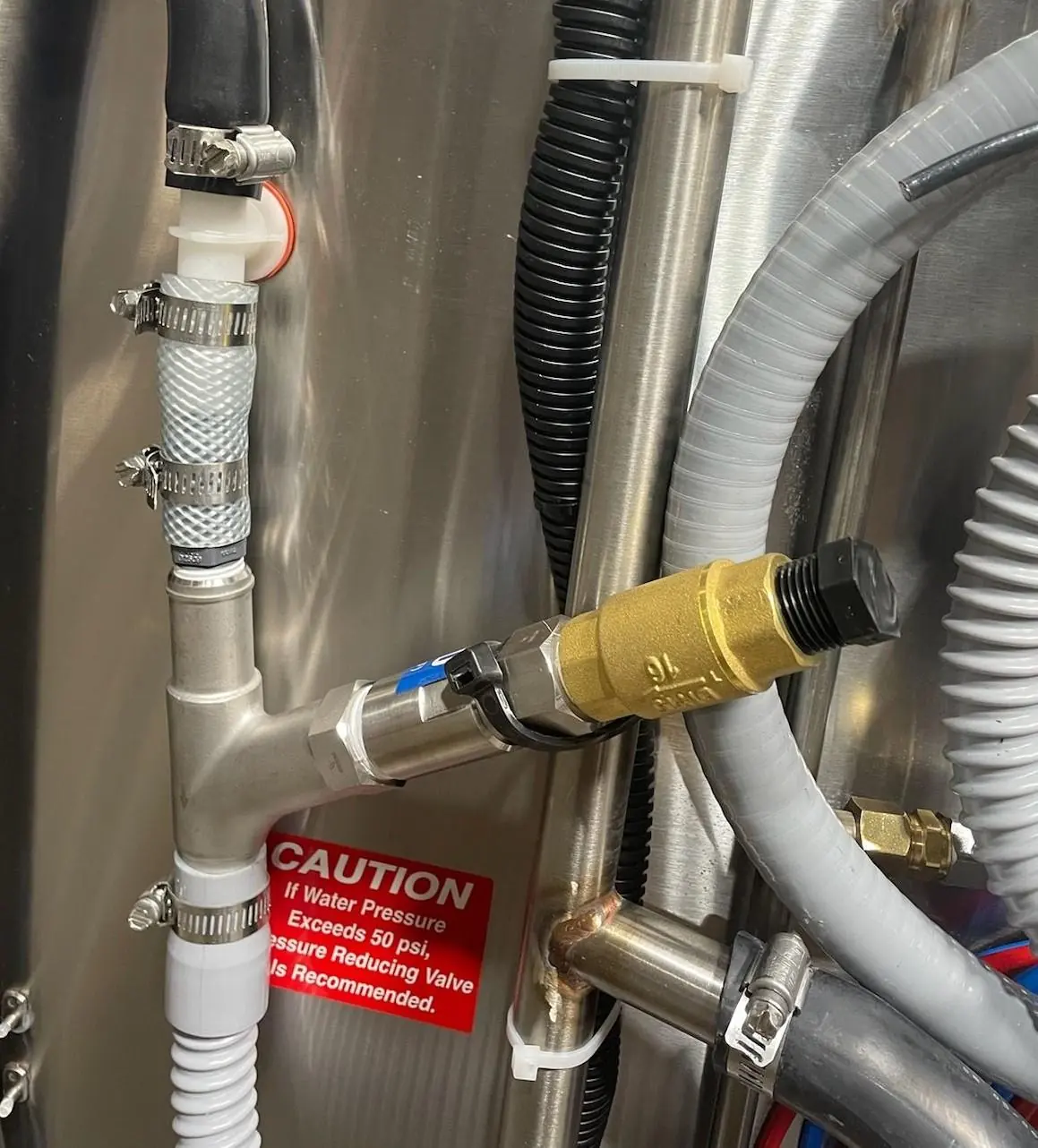
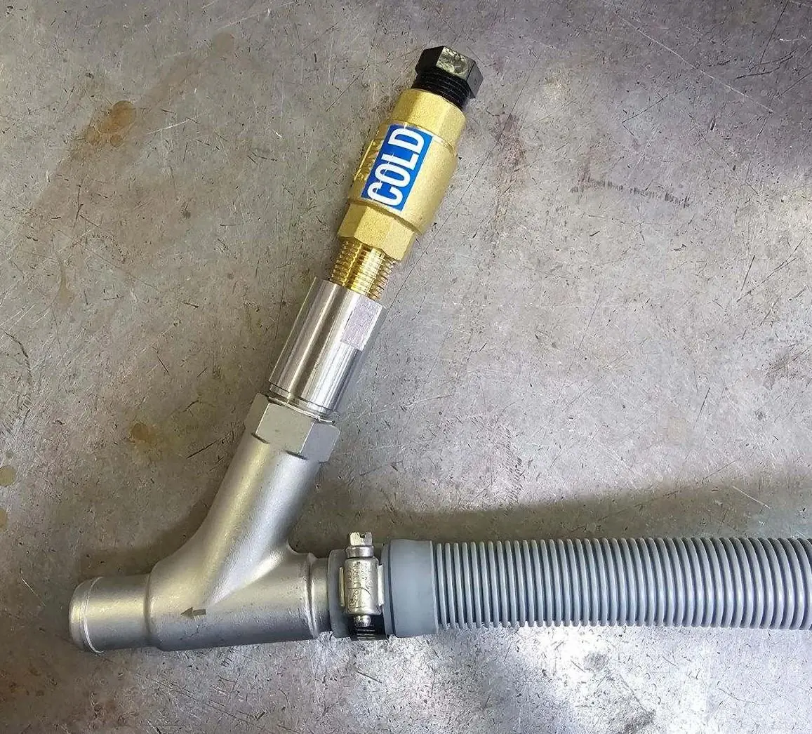
- The wye fitting and CMA Drain Water Tempering valve are already installed.
- Remove the black plug from the valve.
- Connect the cold water line to the in-line check valve.
- Turn on the cold water and check for leaks.
Note: Cold water connections are not supplied by CMA Dishmachines and are the responsibility of the installer.
Field installation
If you are installing the kit in the field:
- Attach the Drain Water Tempering kit to the end of the dishmachine drain line.
- Ensure the assembly is positioned no higher than 12 inches from the floor.
- Remove the black plug.
- Attach the cold water line to the valve.
- Turn on the cold water and check for leaks.
Parts list
The kit consists of the following components:
- DTV "Y" fitting
- Drain Water Tempering Valve
- Nipple Brass 1/2 x 1 1/2 with Flow Disc
- 1/2 Ball Check Valve
- Nipple Brass 1/2 x 2 1/2
- Drain Water Tempering Valve Strainer
- Flow Disc
Important requirements
- Water Pressure: If water pressure exceeds 50 psi, a pressure-reducing valve is recommended.
- Installation Height: The Drain Water Tempering assembly must be no higher than 12 inches from the floor.
- Responsibility: The installer is responsible for the water connection; cold water connections are not supplied by CMA Dishmachines.
Manufacturer information
CMA Dishmachines
Practical help
Common problems
Water pressure exceeds 50 psi
A pressure-reducing valve is recommended to prevent damage or improper operation.
Assembly height issues
Ensure the Drain Water Tempering assembly is installed no higher than 12 inches from the floor.
Before use
- Verify the kit is securely attached to the drain line.
- Ensure the black plug has been removed from the valve.
- Connect the cold water line to the in-line check valve.
- Check all connections for leaks after turning on the water supply.
Images and diagrams
- The parts manual provides an exploded view of the assembly, identifying the Y-fitting, check valve, nipples, and flow disc.
Model compatibility
- Designed specifically for the CMA Dishmachines 180UC-3 model.

Manual page author
Michael Turner
Technical manual editor
Reviews PDF manuals for structure, safety notes, and practical product details so readers can find the right information quickly.