Toys / RC Components
User Manual for Corally TOROX 185-LE Speed Controller
Quick guide for the Corally TOROX 185-LE brushless speed controller. Includes wiring instructions, radio calibration steps, programming settings, and troubleshooting tips.
Quick answers from the manual
Quick answer
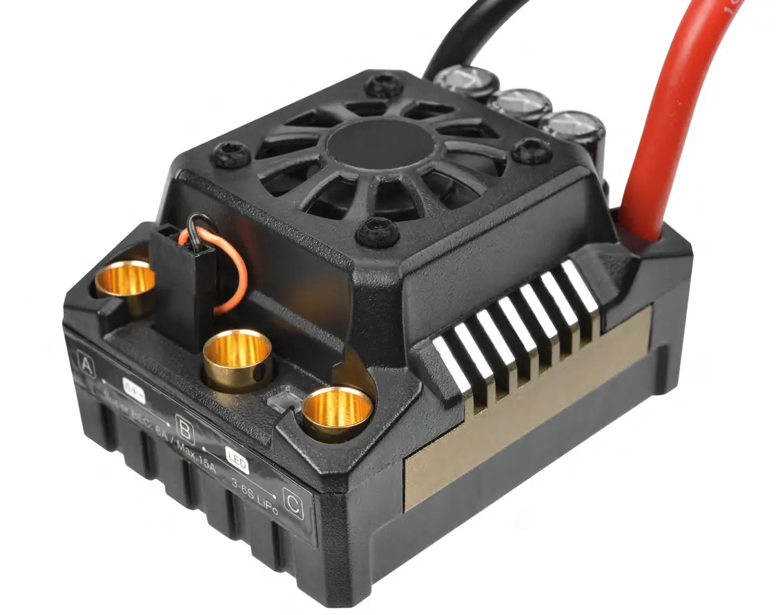
- The Corally TOROX 185-LE is a 185A brushless speed controller for 1/8th scale RC vehicles. It requires radio calibration before first use and supports 3-6S LiPo batteries. p. 1, 2
Key actions
- Calibrate ESC with transmitter p. 3
- Connect motor and battery p. 3
First start
- Connect battery and motor, turn on transmitter, hold SET button while powering on ESC, then calibrate neutral/forward/brake points. p. 3
Problems and fixes
Motor runs in reverse
Swap any two motor wires.
p. 7
ESC enters thermal protection
Let the ESC cool down.
p. 7Maintenance and reset
- Press and hold the SET button for over 3 seconds when the throttle is at neutral to factory reset the ESC. p. 6
Technical specifications
| Parameter | Value | Meaning | Pages |
|---|---|---|---|
| Continuous Current | 185A | Continuous current rating | p. 2 |
| BEC Output | 6V/7.4V | Switchable BEC voltage | p. 2 |
Where to find it in the PDF
- Specifications p. 2
- Connections p. 2, 3
- Radio Calibration p. 3
- Programming p. 4, 5, 6
- Troubleshooting p. 7
Table of contents
Manual images
Click an image to enlargeQuick guide from the manual
The Corally TOROX 185-LE is a high-performance brushless speed controller designed for 1/8th scale RC vehicles. Before operation, ensure all connections are properly insulated and the ESC is calibrated to your transmitter. Important: Do not use 2S LiPo batteries with this ESC. Always disconnect batteries after use to prevent damage.
Connections
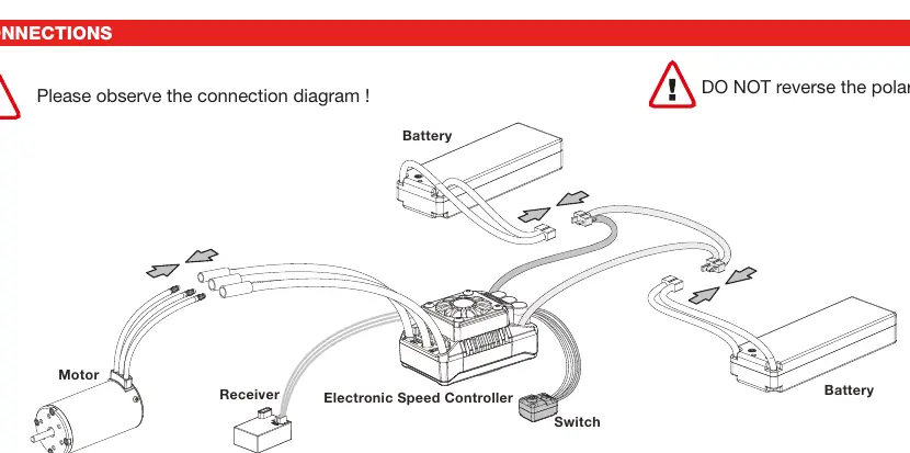
Proper wiring is essential for the safety and performance of your ESC:
- Motor Wiring: There is no polarity on the A/B/C motor wires. If the motor runs in reverse, swap any two of the three motor wires.
- Receiver Wiring: Plug the ESC cable into the Throttle Channel (TH/2) and the steering servo into the Steering Channel (ST/1).
- Battery Wiring: Connect the RED (+) cable to the positive terminal and the BLACK (-) cable to the negative terminal. Warning: Reversing polarity will cause immediate, irreparable damage not covered by warranty.
Radio Calibration
Calibrate the ESC with your transmitter before first use:
- Turn on the transmitter and set throttle parameters (D/R, Curve, ATL) to default (100%). Set throttle trim to 0.
- With the ESC turned off but connected to a battery, hold the SET button and press the ON/OFF button. Release the SET button when the red LED flashes.
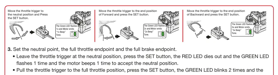
- Set Neutral: Leave the throttle trigger at neutral and press the SET button. The green LED will flash once and the motor will beep once.
- Set Full Throttle: Pull the trigger to full throttle and press the SET button. The green LED will flash twice and the motor will beep twice.
- Set Full Brake: Push the trigger to full brake and press the SET button. The green LED will flash three times and the motor will beep three times.
- The motor can be started 3 seconds after calibration is complete.
Programming
The ESC settings can be adjusted using the SET button. To enter programming mode, hold the SET button while powering on the ESC. You can adjust parameters such as:
- Running Mode: Forward/Brake or Forward/Reverse/Brake.
- LiPo Cells: Auto calculation or manual selection (3S, 4S, 6S).
- Cutoff Voltage: Protects batteries from over-discharge.
- Thermal Protection: Prevents overheating.
- BEC Voltage: Switchable between 6.0V and 7.4V.
- Punch/Start Mode: Adjusts acceleration aggressiveness.
LED Status
The LEDs provide diagnostic information:
- Start-up: Red LED flashing indicates no throttle signal or incorrect neutral value. Green LED flashes indicate the number of LiPo cells detected.
- Operation: Red LED solid indicates forward/reverse/brake activity.
- Protection: Red LED single flash indicates Low Voltage Cutoff. Green LED single flash indicates ESC thermal protection. Green LED double flash indicates Motor thermal protection.
Troubleshooting
If you encounter issues, check the following:
- Motor does not start: Check battery voltage and ensure all connectors are soldered firmly.
- Vehicle runs backward: Swap any two of the three motor wires.
- Motor stutters: Check soldering points between the motor and ESC.
- ESC won't enter programming: Ensure the SET button is released within 3 seconds of powering on.
Practical help
Common problems
Motor does not start, double beep with green LED
Battery voltage is outside the normal operating range. Check battery voltage.
Vehicle runs backward when pulling throttle
Switch any 2 of the 3 motor wires.
Motor stutters but won't start
Check soldering points between motor and ESC; re-solder if necessary.
ESC won't enter programming mode
Ensure SET button is released within 3 seconds of powering on.
Before use
- Ensure all wires are insulated
- Check battery polarity
- Calibrate transmitter throttle
- Set LiPo/NiMH mode
- Set cutoff voltage
Images and diagrams
- Wiring diagram shows connections for Battery, Motor, Receiver, and Switch.
- Calibration diagram shows throttle trigger positions for neutral, full forward, and full brake.
Model compatibility
- Compatible with 1/8th scale Buggy, Truggy, Truck, and On-road vehicles.
- Not compatible with 2S LiPo batteries.
- Requires 60W+ soldering iron for connections.

Manual page author
Michael Turner
Technical manual editor
Reviews PDF manuals for structure, safety notes, and practical product details so readers can find the right information quickly.