Toys / RC Components
FrSky G-RX8 Receiver User Manual
Comprehensive user guide for the FrSky G-RX8 2.4GHz ACCST receiver. Includes instructions for binding, configuring SBUS/PWM modes, setting up failsafe, and using the built-in variometer.
Quick answers from the manual
Quick answer
- To bind the FrSky G-RX8, hold the F/S button on the receiver while connecting the battery, then initiate the bind process on your transmitter. p. 1
Key actions
- Binding the receiver p. 1
- Setting Failsafe p. 1
Problems and fixes
Failsafe not working
Re-bind the receiver and follow the failsafe setup procedure again.
p. 1Technical specifications
| Parameter | Value | Meaning | Pages |
|---|---|---|---|
| Voltage | 4.0-10V | Operating voltage range | p. 1 |
| Weight | 5.8g | Device weight | p. 1 |
Where to find it in the PDF
- User Manual p. 1
Table of contents
Quick guide from the manual
The FrSky G-RX8 is a 16-channel receiver with a built-in variometer. To bind the receiver, turn on your transmitter, connect the battery to the receiver while holding the F/S button, and follow the transmitter's binding procedure. The receiver supports both SBUS and PWM modes, which can be toggled by the user.
Binding Procedure
To bind the receiver to your transmitter:
- Put the transmitter module into binding mode (refer to your transmitter manual for specific steps, e.g., MENU - MODEL SETUP - PAGE 2).
- Connect the battery to the receiver while holding the F/S button.
- The red LED on the receiver will flash, indicating the binding process is complete.
- Turn off both the transmitter and the receiver.
- Turn on the transmitter and connect the battery. The green LED on the receiver will flash, indicating the binding is successful.
Configuration
SBUS / PWM Mode
To switch between SBUS and PWM modes:
- SBUS Mode: If the blue LED is on the receiver, it is in SBUS mode.
- PWM Mode: If the blue LED is off, it is in PWM mode.
- To switch, turn on the receiver. If the blue LED is on, it stays in SBUS mode. If it is off, it stays in PWM mode.
Altimeter Function
The altimeter is enabled by default. To disable it:
- Bring the receiver into normal operational mode.
- Hold the F/S button for more than 3 seconds.
- The blue LED will flash 3 times to confirm the function has been toggled.
Channel Output (1-8CH / 9-16CH)
The receiver defaults to 1-8CH output. To switch to 9-16CH:
- Connect CH3 and CH4 using a jumper.
- Perform the binding process.
- After successful binding, the output channel will change.
Failsafe
Failsafe is a useful feature that sets a preset position for all channels when the control signal is lost. To set the failsafe:
- Bind the receiver and turn on both the transmitter and receiver.
- Move the controls to the desired failsafe position for all channels.
- Press the F/S button on the receiver for less than 1 second. The green LED will flash, indicating the position has been set.
Alternatively, you can set the failsafe via your transmitter settings if supported.
Technical Specifications
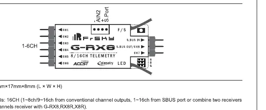
- Dimensions: 55.26mm x 17mm x 8mm
- Weight: 5.8g
- Operating Voltage Range: 4.0-10V
- Operating Current: 100mA@5V
- Channels: 16CH (1-8CH or 9-16CH via SBUS)
- Variometer Sensor: -700m to 10000m with 0.1m precision
Manufacturer information
FrSky Electronic Co., Ltd.
Practical help
Common problems
Receiver not binding
Ensure the transmitter is in the correct binding mode and the F/S button is held down while connecting the battery.
Failsafe not set correctly
Re-bind the receiver and ensure the transmitter controls are in the desired position before pressing the F/S button.
Before use
- Verify operating voltage is between 4.0V and 10V.
- Ensure the transmitter is compatible with ACCST protocol.
- Check antenna placement for optimal signal reception.
- Confirm if you need SBUS or PWM mode for your servos/flight controller.
Specs in practice
- Operating Voltage
- The receiver requires 4.0V to 10V DC power.
Images and diagrams
- The wiring diagram illustrates the connection points for SBUS In, SBUS Out, and the F/S button.
- It shows the pinout for channels 1-6 and the telemetry port.
Model compatibility
- Compatible with FrSky ACCST transmitters.
- Supports redundancy function with other FrSky receivers.

Manual page author
Emily Carter
User documentation editor
Prepares concise manual descriptions and highlights the most useful setup, operation, and maintenance information for readers.