Toys / RC Components
User Guide for Spektrum SLT3 Transmitter
A comprehensive user guide for the Spektrum SLT3 2.4GHz Digital Radio System. Includes instructions for battery installation, receiver binding, servo travel adjustment, factory reset, and troubleshooting.
Quick answers from the manual
Quick answer
- To bind the receiver, press and hold the bind button while powering on the receiver, then power on the transmitter. A solid orange LED on the receiver confirms the connection. p. 3
Key actions
- Binding the receiver p. 3
- Adjusting Servo Travel p. 3
- Factory Reset p. 4
First start
- Install 4 AA batteries into the transmitter. p. 1
Problems and fixes
System will not connect
Move transmitter 1 to 3 meters from receiver; move to an area with less metal.
p. 4Maintenance and reset
- Factory Reset: Hold full left and full brake while powering on, then release to neutral. p. 4
Technical specifications
| Parameter | Value | Meaning | Pages |
|---|---|---|---|
| Power Supply | 4 AA Batteries | Required power source for the transmitter. | p. 1 |
| Receiver Voltage Range | 3.5–9.6V | Operating voltage range for the SR315 receiver. | p. 3 |
Where to find it in the PDF
- Transmitter Functions p. 1
- Receiver and Binding p. 3
- Troubleshooting and Warranty p. 4
Table of contents
Manual images
Click an image to enlargeQuick guide from the manual
The Spektrum SLT3 is a 2.4GHz digital radio system designed for hobby-grade, remote-controlled vehicles. This guide covers the essential setup, including battery installation, binding the receiver, and adjusting servo travel. Always ensure your batteries are charged and the receiver antenna is correctly positioned (not in the shadow of metal or carbon fiber) before operation.
Transmitter Functions
The SLT3 transmitter features several controls for fine-tuning your vehicle:
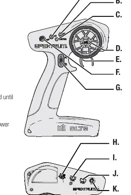
- Steering Trim (B): Adjusts the steering center point.
- Throttle Trim (A): Adjusts the throttle neutral point.
- Steering Rate (F): On-the-fly knob for travel adjustment.
- Throttle Limit (H): Limits output to 50%, 75%, or 100%.
- Servo Reversing (I, J): Switches to reverse throttle or steering channels.
- LED (C): Solid red indicates power ON; flashing red indicates low battery.
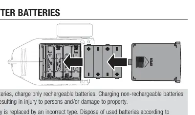
Installing the Transmitter Batteries
- Remove the battery cover from the transmitter.
- Install 4 AA batteries, ensuring correct polarity as shown in the diagram.
- Replace the battery cover.
Caution: Do not charge non-rechargeable batteries. Use only the correct battery type to avoid explosion risks.
Binding the Receiver
Binding programs the receiver to recognize the specific transmitter.
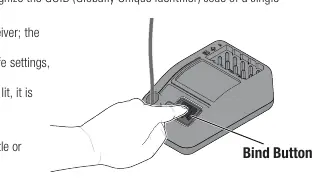
- Press and hold the bind button on the receiver, then power ON the receiver. The orange LED will flash.
- Set trims and control positions to desired failsafe settings.
- Power ON the SLT3 transmitter.
- When the orange LED on the receiver remains lit, the connection is established.
You must rebind if you change failsafe positions or bind to a different transmitter.
Servo Travel Adjustment
You can adjust the steering and throttle travel limits:
- Complete the binding process and power ON the receiver.
- Hold full right and full brake while powering the transmitter ON. The LED will flash 4 times to indicate programming mode.
- Turn the wheel full left to set the limit for that direction. Use the A button to increase travel or the B button to reduce it.
- Return the wheel to center to set the value.
- Repeat the process for the right side.
- Power the transmitter OFF to save settings.
Factory Reset
To reset servo travel and calibration:
- Hold full left and full brake while powering the transmitter ON. The LED will flash 4 times and then turn OFF.
- Release the wheel and throttle trigger to neutral; the LED will illuminate.
- Power the transmitter OFF.
Troubleshooting
If the system fails to connect, ensure the transmitter and receiver are 1 to 3 meters apart and away from metal objects. If the receiver loses connection or enters failsafe mode, check that the antenna is not cut or damaged and is positioned in an antenna tube above the vehicle. Ensure the power supply is at least 3.5V.
Manufacturer information
Spektrum
Practical help
Common problems
System will not connect
Move transmitter 1 to 3 meters away from the receiver and ensure you are not near large metal objects.
Receiver enters failsafe mode at short distance
Check the receiver antenna for cuts or damage. Ensure it is placed in an antenna tube and positioned above the vehicle.
Receiver quits responding during operation
Check battery voltage (must be at least 3.5V) and inspect wires/connectors between battery and receiver.
Before use
- Ensure all batteries are properly charged.
- Check all servos and their connections.
- Ensure the receiver antenna is not in the shadow of carbon fiber or metal.
- Verify the transmitter and receiver are bound correctly.
Specs in practice
- Operating Frequency
- 2.4GHz, the standard frequency for this radio system.
- Control Protocol
- SLT, the communication language between transmitter and receiver.
- Receiver Voltage Range
- 3.5–9.6V; the receiver requires at least 3.5V to operate.
Images and diagrams
- Transmitter controls diagram showing locations of trims, steering wheel, and switches.
- Battery installation diagram showing the 4 AA battery orientation.
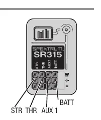
- Receiver diagram showing port locations for STR, THR, AUX1, and BATT.
Model compatibility
- SR315 receivers included with the SLT3 are SLT and DSMR compatible.
- Standalone SR315 receivers may require a firmware update for SLT compatibility.

Manual page author
Michael Turner
Technical manual editor
Reviews PDF manuals for structure, safety notes, and practical product details so readers can find the right information quickly.