Garden / Lawn Mowers
Operating and Maintenance Instructions for COX Compact Tractors 928 Series 2 & 2/K1
Comprehensive operating and maintenance guide for COX 928 Series 2 and 2/K1 compact tractors. Includes detailed parts lists, exploded diagrams, and essential maintenance procedures.
Quick answers from the manual
Quick answer
- This manual provides operating and maintenance instructions for COX 928 Series 2 and 2/K1 compact tractors, including detailed parts lists and exploded diagrams for chassis, steering, and drive components. p. 1, 12, 13
Key actions
- Start the engine p. 12
- Adjust cutting height p. 12
First start
- Ensure mower attachment is disengaged before starting the engine. p. 12
Technical specifications
| Parameter | Value | Meaning | Pages |
|---|---|---|---|
| Tyre Pressure | 15 PSI | Recommended pressure for front and rear tyres. | p. 13 |
| Lubrication Interval | 25 hours | Frequency for machine lubrication. | p. 13 |
Where to find it in the PDF
- Operating Instructions p. 12
- Maintenance Instructions p. 13
- Parts Lists p. 2, 3, 4, 5
Table of contents
Manual images
Click an image to enlargeImportant Information
This manual covers the operation and maintenance of COX 928 Series 2 (1978-1981) and 928 Series 2/K1 (1981-1983) compact tractors. It is the owner's responsibility to ensure all periodical checks, adjustments, and services are carried out. Always use genuine COX factory spare parts to maintain warranty and performance.
Operating Instructions
Before Starting: Ensure the mower attachment is disengaged before starting the engine. For machines fitted with Micro Switches, place your heel on the micro switch located on the rear of the footrest to engage the starter.
Driving: Power is regulated by the throttle. Use the clutch pedal to control forward and reverse movement. Press the forward section of the clutch pedal for forward movement and the rear section for reverse.
Braking: When the engine is running, use the clutch pedal to stop the machine. If travelling forward, push the pedal into reverse until the machine stops, then bring it to the neutral position. The parking brake should only be used when the engine is stopped.
Cutting Height Adjustment: The height adjustment lever is located on the left-hand side of the machine and can be adjusted while the machine is in motion.
Maintenance Instructions
General Maintenance: Stop the engine and remove the spark plug lead before attempting any form of service or adjustment. Ensure the blades have stopped rotating.
- Oil Changing: Carry out as per engine manufacturer recommendations.
- Lubrication: Perform every 25 hours of operation. Oil steering, linkages, steering column shaft, height adjustment mechanism, and pivot bolts. Use grease nipples on front axle kingpin bushes with Ampol MP red grease.
- Blade Maintenance: Check blades with the engine stopped. Lift the machine and rest on a block. Remove the windrower and set the height adjustment to the highest position to access the blades.
- Belt Adjustment: Loosen the four engine mounting bolts and move the engine to correct belt tension.
- Tyre Pressures: Maintain approximately 15 PSI for both front and rear tyres.
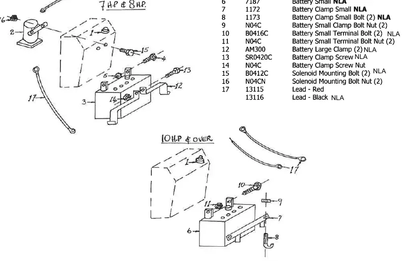
- Battery: Maintain electrolyte fluid level just above the plates by topping up regularly with distilled water.
Parts Identification
The manual includes detailed exploded view diagrams for the following groups:
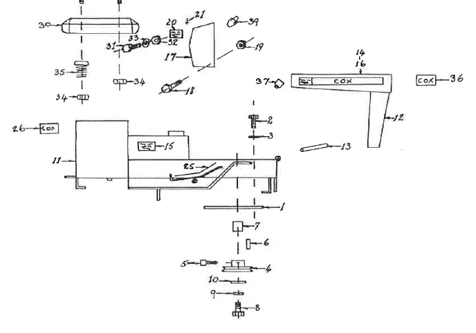

- Chassis and Components
- Right and Left Side of Chassis
- Electrical Components
- Steering Components
- Front and Rear Wheel Components
- Drive Components
- Clutch Arm and Components
- Mowing Attachment Components
Practical help
Common problems
Mower attachment will not engage
Ensure the mower is disengaged before starting the engine.
Uneven cutting finish
Check that tyre pressures are set to 15 PSI.
Before use
- Check all bolts and nuts after the first hour of running.
- Ensure the mower attachment is disengaged before starting.
- Check tyre pressures (15 PSI).
- Ensure battery electrolyte level is correct.
- Check that the parking brake is disengaged before driving.
Specs in practice
- Tyre Pressure
- 15 PSI for both front and rear tyres.
- Lubrication Interval
- Every 25 hours of operation.
Images and diagrams
- The manual provides exploded view diagrams for each component group, with reference numbers corresponding to the parts list tables.
Model compatibility
- 928 Series 2 (1978-1981) and 928 Series 2/K1 (1981-1983) have specific part variations; refer to the correct table for your model.

Manual page author
Michael Turner
Technical manual editor
Reviews PDF manuals for structure, safety notes, and practical product details so readers can find the right information quickly.