Electronics / Networking
User Manual for D-Link DFE-855 Series Fiber Interface Converter
Quick installation guide and technical specifications for the D-Link DFE-855 Series Fiber Interface Converter. Learn how to connect UTP and fiber cables, interpret LED status indicators, and understand device requirements.
Table of contents
Manual images
Click an image to enlargeQuick guide from the manual
This document provides installation and operation instructions for the D-Link DFE-855 Series Fiber Interface Converters. These devices allow for the extension of 10/100Mbps Ethernet cabling distances up to 120 kilometers using fiber optic technology. The guide covers connection procedures, LED status interpretation, and technical specifications.
Installation
Follow these steps to install the fiber interface converter:
- Connect the fiber interface cables to the DFE-855 unit.
- Use a straight or cross UTP cable to connect the Ethernet connection to the appropriate RJ-45 jack.
- Install the fiber converter using the provided AC power adapter (9V 1A).
- Ensure the environment meets the operating requirements (0-50°C, 10-90% humidity).
Connections
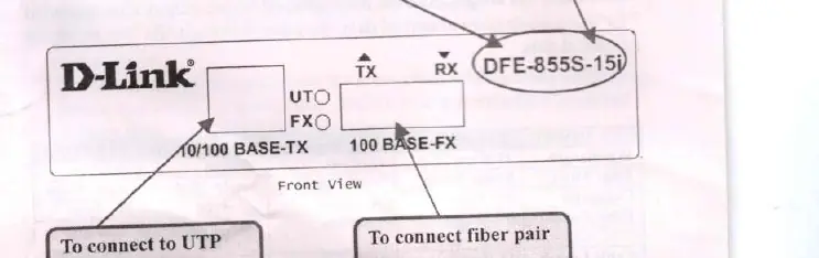
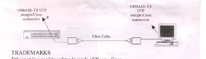
The device features SC connectors for fiber optic cable and RJ-45 ports for UTP cable. The converter supports 100BASE-TX to 100BASE-FX conversion. When connecting from a 100BASE-TX port of a HUB to a 100BASE-TX Network Interface Card (NIC) in a computer, ensure the UTP cabling is configured correctly (straight/cross connection as required).
LED Indicators
Use the LED indicators to identify the status of your connection:
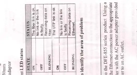
- FX (Fiber Link): ON indicates the fiber link is OK. OFF indicates the link is faulty. BLINKING indicates the device is receiving data on the fiber.
- UT (Ethernet Link): ON indicates the UTP link is OK. OFF indicates the link is faulty. BLINKING indicates the device is receiving data on the Ethernet.
Specifications
- Standards: IEEE802.3u 100BASE-TX, 100BASE-FX.
- UTP Cable: Category 5e, maximum distance 100 meters (328 feet).
- Power: 9V 1A AC/AC adapter.
- Environment: 0-50°C, 10-90% non-condensing humidity.
- Compatibility: Supports Full Duplex Ethernet mode (200Mbps). Can be used with D-Link Fiber Rack DFE-RA12-A2+.
Manufacturer information
D-Link Corporation
Practical help
Common problems
Fiber Link LED is OFF
The fiber link is faulty. Check the fiber cable connection.
Ethernet Link LED is OFF
The UTP link is faulty. Check the UTP cable connection.
Before use
- Ensure you have a 9V 1A AC/AC power adapter.
- Verify you have the correct fiber cable (SC connector).
- Use Category 5e UTP cable for Ethernet connections.
- Check the distance requirements for your specific model (15km, 50km, or 120km).
Images and diagrams
- The front view shows the TX and RX ports for fiber and the UTP port.
- The connection scheme illustrates connecting a HUB to a NIC via the fiber converter.
Model compatibility
- Supports Full Duplex Ethernet mode (200Mbps).
- Compatible with D-Link Fiber Rack DFE-RA12-A2+.

Manual page author
David Miller
Documentation analyst
Organizes user manual content into clear summaries, with attention to model details, product context, and everyday usability.