Electronics / Networking
D-Link JustConnect 16-Channel PoE Network Video Recorder Installation Guide
Quick installation guide for the D-Link JustConnect 16-Channel PoE Network Video Recorder (DNR-2020-04P). Includes hardware setup, hard drive installation, and initial configuration steps.
Table of contents
Manual images
Click an image to enlargeQuick guide from the manual
This document provides instructions for setting up the D-Link DNR-2020-04P JustConnect 16-Channel PoE Network Video Recorder. The guide covers unpacking, hardware installation, connecting cameras, and initial configuration.
Unpacking the product
Ensure all items are present and undamaged before starting installation:
- DNR-2020-04P Network Video Recorder
- Hard disk screws (x8)
- Rackmount brackets (x2)
- Rackmount bracket screws (x8)
- Power adapter and cable
- Ethernet cable (CAT5 UTP)
- Quick Installation Guide
- CD-ROM with applications and documentation
Front panel overview
The front panel features status LEDs and control ports:
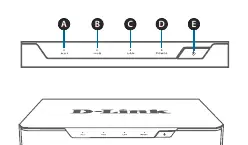
- HDD1/HDD2 LED: Solid green indicates proper installation. Blinking indicates read/write activity. Red indicates a failed drive.
- LAN LED: Solid green indicates network connection. Blinking indicates data transfer.
- Power LED: Solid green indicates the device is powered on.
- Power Button: Push for one second to power on; push for 5 seconds or more to power off.
- USB 2.0 Port: Used for connecting a mouse/keyboard for UI control or a flash drive/USB hard disk for backups and firmware upgrades.
Back panel overview
The back panel provides connectivity for cameras and peripherals:
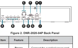
- Power Input: Connect the supplied power cord.
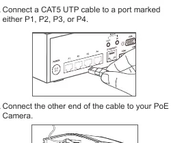
- PoE Ports 1-4: Connect cameras using CAT5 Ethernet cables.
- Audio In/Out: Connect a microphone and external speakers.
- Gigabit Ethernet Port: Connect to your router or switch.
- HDMI/VGA Output: Connect to a monitor for local display.
- USB 3.0 Port: For external storage or control peripherals.
- DI/DO: Connect four DI trigger devices and one DO device.
- Reset Button: Press and hold for 10 seconds to reset to factory defaults.
Hardware installation
Follow these steps to install hard drives:
- Remove the screws from the sides and back of the device to access the HDD bays.
- Slide the cover rearward to remove it.
- Detach the HDD bay bracket and insert one or two 3.5-inch SATA hard drives. Secure them with the provided screws.
- Connect the power and SATA cables from the device to each HDD. The HDD LED should light up if installed correctly.
- Re-attach the drive bay bracket and the top cover, securing them with the screws.
Configuration
To set up the NVR:
- Connect the power adapter and switch on the device.
- Ensure the NVR is connected to your network via a router or switch.
- Insert the provided CD into a PC. If it does not autorun, run D:\autorun.exe.
- Select NVR Search Utility to find your device on the network.
- Click Configuration to access the web UI.
- Log in using the username admin (leave the password blank).
- Follow the setup wizard to complete the configuration.
Technical support
If you encounter issues, visit the D-Link support website at http://support.dlink.com (US) or http://support.dlink.ca (Canada) for the latest documentation and software updates.
Official resources from the manual
Manufacturer information
D-Link Corporation
Practical help
Common problems
HDD LED is red
The hard drive is installed but has failed.
Power LED is off
The device is not powered on. Check the power adapter connection.
LAN LED is off
The device is not connected to the network. Check the Ethernet cable connection.
PoE LED is off
There is no power to the camera. Ensure the cable is connected correctly.
Before use
- Verify all items from the packing list are present.
- Ensure you have 3.5-inch SATA hard drives available.
- Have a Phillips screwdriver ready for the case screws.
- Ensure a network router or switch is available for connection.
- Have a monitor (HDMI or VGA) and a USB mouse if performing local setup.
Images and diagrams
- Front panel includes HDD status LEDs, LAN/Power indicators, power button, and a USB 2.0 port.
- Back panel includes power input, 4 PoE ports, Audio I/O, Gigabit Ethernet, HDMI/VGA outputs, USB 3.0, DI/DO, grounding port, and reset button.
Model compatibility
- Supports 3.5-inch SATA hard drives.
- Total PoE budget is limited to 45 watts.
- Requires CAT5 UTP cable for camera connections.

Manual page author
David Miller
Documentation analyst
Organizes user manual content into clear summaries, with attention to model details, product context, and everyday usability.