Electronics / Networking
Digitus 16-Port Industrial Ethernet Switch User Guide
Quick installation guide for the Digitus 16-Port Industrial Ethernet Switch (DN-651138). Includes installation steps, power connection, LED indicators, and technical specifications.
Table of contents
Manual images
Click an image to enlargeQuick guide from the manual
The Digitus DN-651138 is an industrial-grade Ethernet switch designed for harsh environments with an operating temperature range of -40°C to 80°C. It features 16 ports (10/100/1000Base-TX) and 2 Gigabit SFP ports. The device supports DIN rail and wall mounting, dual power input redundancy, and is housed in an IP40-rated aluminum casing. Note that this model does not support PoE (Power over Ethernet).

Switch Panel
The device features a side panel and a front panel:

- Side Panel: Contains P1 and P2 power terminals, an alarm interface (F), and an earthing screw for grounding.
- Front Panel: Houses the 16 RJ45 ports and 2 SFP ports. Each RJ45 port has a yellow LED indicator for link and data transmission status.
Installation
Follow these steps for proper setup:
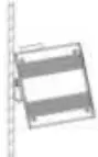
- DIN Rail Installation: Ensure the guide rail is stable and grounded. Clamp the switch onto the rail, secure it with positioning screws from the center outwards, and fix the mounting rail card slot at both ends to ensure vertical stability.
- Grounding: Connect a grounding wire to the grounding screw located above the switch to ensure a reliable connection to the grounding system.
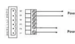
- Power Connection: Insert the power cord into the 6-core terminal block. Connect the positive and negative poles to the P+1/P-1 (Power 1) and P+2/P-2 (Power 2) inputs. The switch supports a voltage range of 12VDC to 52VDC.
LED Indicators
Monitor the switch status using the following LED definitions:
- P1/P2 (Red LED): On indicates normal power supply; Off indicates abnormal power supply or no power.
- RJ45 Indicator (Yellow LED): On indicates a normal network connection; Flashing indicates active link communication; Off indicates no connection.
Technical Specifications
- Standards: IEEE802.3, 802.3i, 802.3u, 802.3ab, 802.3z, 802.3x.
- Interfaces: 16-Port RJ45, 2-Port SFP Uplink.
- Power Supply: 12-52VDC (dual power redundancy), built-in 4.0A over-current protection.
- Mechanical: IP40 aluminum housing, natural cooling (fanless), weight 1.0kg.
- Environment: Operating/Storage temperature -40°C to 80°C, Humidity 5% to 95% (non-condensing).
Practical help
Common problems
Power LED (P1/P2) is off
Check the power supply connection and ensure the input voltage is within the 12-52VDC range.
No network connection
Verify the RJ45 cable is properly connected and the yellow link LED is active.
Radio interference in home environment
This is a Class A product; ensure proper grounding and shielding as it may cause interference in residential areas.
Before use
- Verify power supply voltage is between 12VDC and 52VDC.
- Ensure the DIN rail is stable and properly grounded.
- Use Class 5 shielded twisted pair cables for Ethernet connections.
- Confirm the environment is free from excessive dust and strong electromagnetic interference.
- Ensure the device is mounted in a stable position.
Specs in practice
- Operating Temperature
- -40°C to 80°C, suitable for industrial, harsh environments.
- IP40 Housing
- Protection against solid objects larger than 1mm; not waterproof.
- Surge Protection
- 5000A (8/20μs) on power lines to protect against lightning surges.
Images and diagrams
- Side panel diagram illustrates the terminal block layout for P1/P2 power inputs and the alarm interface.
- Front panel diagram shows the port layout and LED indicator locations.
- Power connection diagram details the 6-core terminal block wiring for dual power inputs.
Model compatibility
- Not compatible with PoE (Power over Ethernet).
- Supports DIN rail and wall mounting.
- Compatible with standard 10/100/1000Base-TX Ethernet devices.

Manual page author
Emily Carter
User documentation editor
Prepares concise manual descriptions and highlights the most useful setup, operation, and maintenance information for readers.